
Thermal photovoltaic power generation device

A thermal photovoltaic power generation and photovoltaic cell technology, applied in photovoltaic power generation, photovoltaic power stations, photovoltaic modules, etc., can solve the problems of complex wiring, short battery life, and not easy to carry, etc., to increase system efficiency, reduce intermediate links, and energy utilization. high rate effect

Inactive Publication Date: 2016-07-20
SUZHOU UNIV
View PDF6 Cites 8 Cited by
  • Summary
  • Abstract
  • Description
  • Claims
  • Application Information

AI Technical Summary

Problems solved by technology

Among them, solar power is used to convert solar energy into electrical energy by using the photovoltaic effect of solar panels, and then use the control system including the storage battery to realize independent power supply, but it cannot supply power when it encounters rainy weather or at night. Therefore, the solution has a volume Large, low energy conversion efficiency per unit area and greater environmental impact; diesel generators have high energy consumption, low safety, complex wiring, bulky and difficult to carry, and poor adaptability to complex working environments in the field, etc. In addition, the battery system as a passive power supply solution has limitations such as short battery life, difficulty in charging in an outdoor environment, and heavy weight
There are also some that combine solar power and wind power, but they also have defects such as large size.
[0004] Therefore, in view of the above technical problems, it is necessary to provide an outdoor power supply system that is easy to carry, has high energy output density, is not affected by the environment and has a long battery life, so as to solve the current difficult problem of outdoor power supply and improve the quality of power supply

Method used


Image

  • Thermal photovoltaic power generation device

Examples


Embodiment Construction

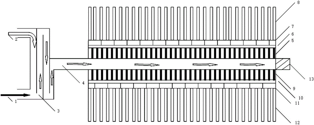
[0028] In order to enable those skilled in the art to better understand the technical solutions in the present invention, the technical solutions in the embodiments of the present invention will be clearly and completely described below in conjunction with the drawings in the embodiments of the present invention. Obviously, the described The embodiments are only some of the embodiments of the present invention, not all of them. Based on the embodiments of the present invention, all other embodiments obtained by persons of ordinary skill in the art without making creative efforts shall fall within the protection scope of the present invention.

[0029] A thermal photovoltaic power generation device of the present invention includes an air inlet, and the air inlet can be one or two, and two air inlets are preferably used, which are respectively the first air inlet 1 and the second air inlet 2. The photovoltaic power generation device also includes a premixer 3 and a burner 4. Th...


PUM


Abstract

The invention discloses a thermal photovoltaic power generation device, which comprises air inlets, a premixer and a combustor, wherein radiators and photovoltaic cell assemblies are sequentially arranged on the periphery of the combustor; fuel enters the premixer and the combustor through the air inlets for premixing and combustion respectively; the radiators absorb heat energy from the combustor and release heat radiation to the photovoltaic cell assemblies; and the photovoltaic cell assemblies absorb the heat radiation and convert the heat radiation into electric energy. The thermal photovoltaic power generation device combines a thermo-photovoltaic technology, a near-field radiation technology and a metamaterial radiation technology, has a simple and stable mechanical structure, can relatively well adapt to an outdoor complex and volatile working environment, achieves miniaturization and modularization of equipment when ensuring stable power supply, and has the advantages of being simple in structure, convenient to carry, high in power generation power per unit volume, high in safety, long in lifetime and the like; and the energy conversion efficiency and the portability of the equipment are considered.

Description

technical field [0001] The invention relates to the field of thermal photovoltaic power supply, in particular to a miniature thermal photovoltaic power generation device. Background technique [0002] With the increasing popularity of outdoor sports and the popularization of electronic products, people's demand for electric energy in the wild is also increasing. [0003] The traditional field power supply schemes mainly include solar power supply, diesel generator set power supply and battery power supply. Among them, solar power is used to convert solar energy into electrical energy by using the photovoltaic effect of solar panels, and then use the control system including the storage battery to realize independent power supply, but it cannot supply power when it encounters rainy weather or at night. Therefore, the solution has a volume Large, low energy conversion efficiency per unit area and greater environmental impact; diesel generators have high energy consumption, lo...

Claims


Application Information

Patent Timeline
Patent Type & Authority Applications(China)
IPC IPC(8): H02S10/30
CPCH02S10/30Y02E10/50
Inventor 徐其琛张晓静吴玺
Owner SUZHOU UNIV
Learn More