

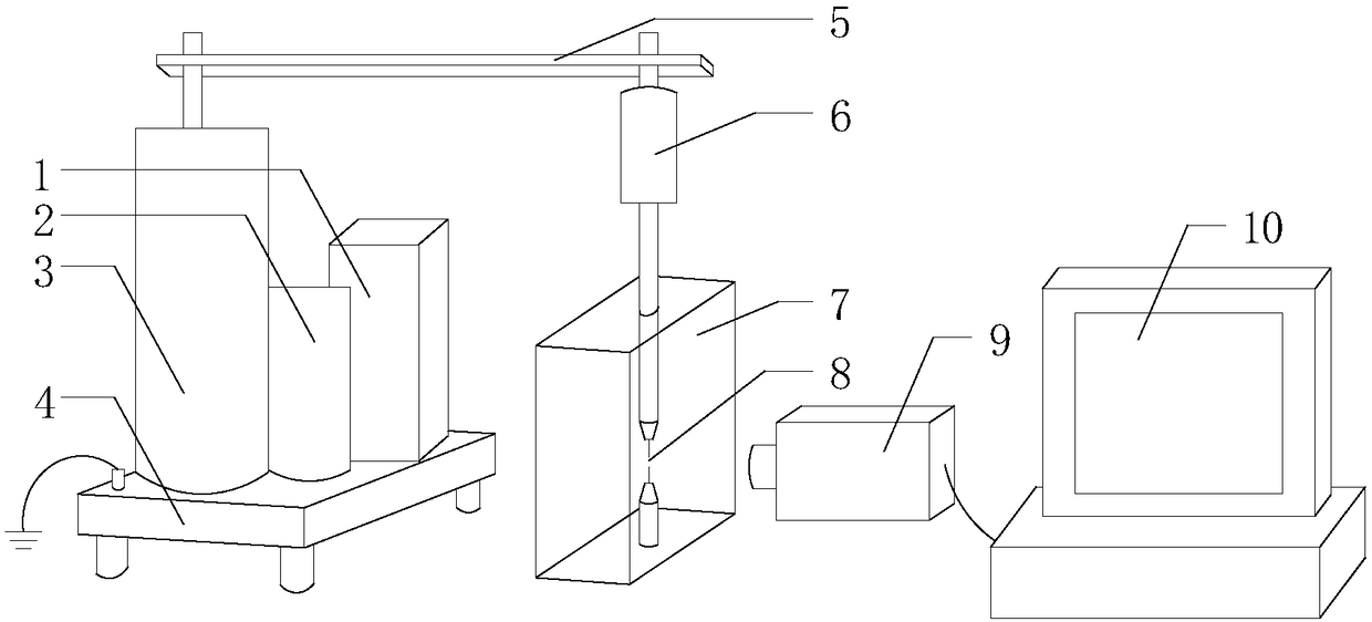
Experimental device for generating cavitation bubbles based on electric spark
An experimental device and cavitation bubble technology, which is applied to pressure vessels used in chemical processes, pressure vessels/vacuum vessels, etc., can solve problems such as low device safety, connection interference, and potential safety hazards, so as to simplify test operations and avoid short circuits Dangerous, mechanical strength enhancement effect
- Summary
- Abstract
- Description
- Claims
- Application Information
AI Technical Summary
Problems solved by technology
Method used
Image

Examples
Embodiment
[0041] In this embodiment, the civilian 220V alternating current is selected as the power supply for the whole device, and the high leakage reactance test transformer 1, the high-speed camera 9, and the computer system 10 are connected respectively; distance from the magnifying lens; the computer system 10 is preinstalled with image processing software, and its image processing software is PFV3.6.4.
[0042] The specific values of the output four-level voltage of the high leakage reactance test transformer 1 are 15.76kV, 18.2kV, 21.4kV, and 25.6kV respectively; The rectification device 2 can obtain four sets of DC high voltage voltages of 19.7kV, 23.0kV, 27.5kV and 33kV.
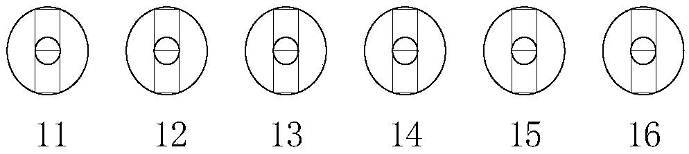
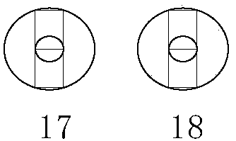
[0043] The five resistance values of the resistance bridge 5 are as follows: the first tap 19 of the resistance is 400 Ω, the second tap 20 of the resistance is 500 Ω, the third tap 21 of the resistance is 600 Ω, the fourth tap 22 of the resistance is 700 Ω and the fifth tap 23 of the resistance is 800Ω...
PUM
 Abstract
Description
Claims
Application Information