
Circulating cooling water bypass flow water treatment system and bypass flow water treatment method

A technology of circulating cooling water and flowing water treatment, applied in water/sewage treatment, water/sewage multi-stage treatment, water/sludge/sewage treatment, etc., can solve problems such as large fluctuation range, intensified corrosion, and inability to online disinfection

Active Publication Date: 2016-07-27
章明歅 +1
View PDF5 Cites 12 Cited by
  • Summary
  • Abstract
  • Description
  • Claims
  • Application Information

AI Technical Summary

Problems solved by technology

The circulating cooling water will inevitably cause a series of hazards to the heat exchange equipment during the circulating operation, that is, the deposition of scale and dirt, the intensification of corrosion, the growth of bacteria and algae, etc. If effective treatment is not carried out, the circulating cooling water system will be very serious. hard to run
[0004] At present, the existing technology adopts the method of adding chemical agents to deal with the problems of scale, dirt deposition, intensified corrosion, and the growth of bacteria and algae in circulating cooling water. However, the traditional method of adding chemicals cannot be sterilized on-line. Intermittent dosing, microorganisms will breed between two dosing, causing problems of microorganisms and suspended solids; sewage is also intermittent sewage, calcium carbonate saturation index LSI and stability index RSI fluctuate widely, and scaling and corrosion are difficult to obtain stable control

Method used

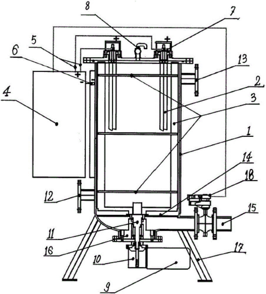
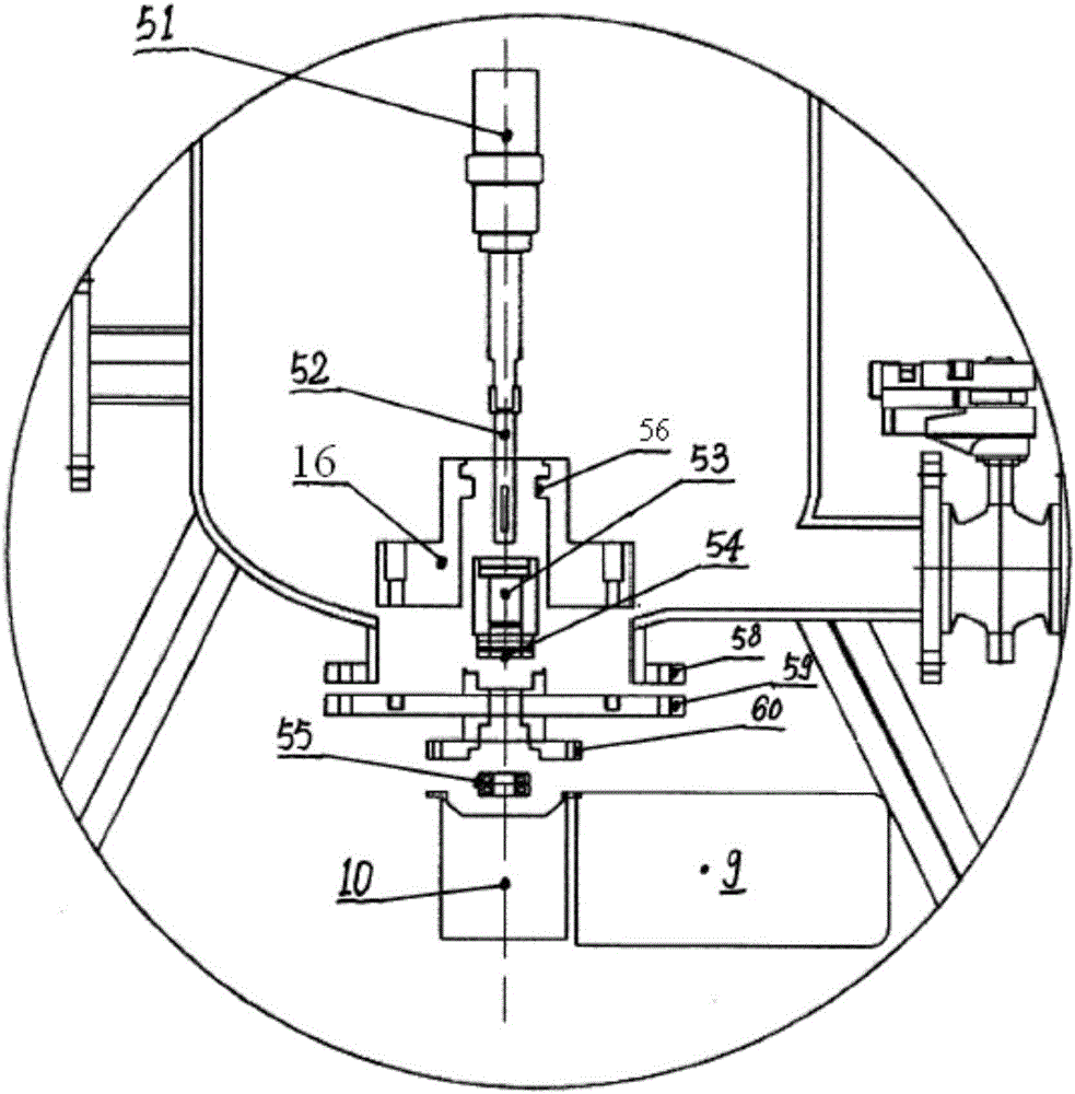
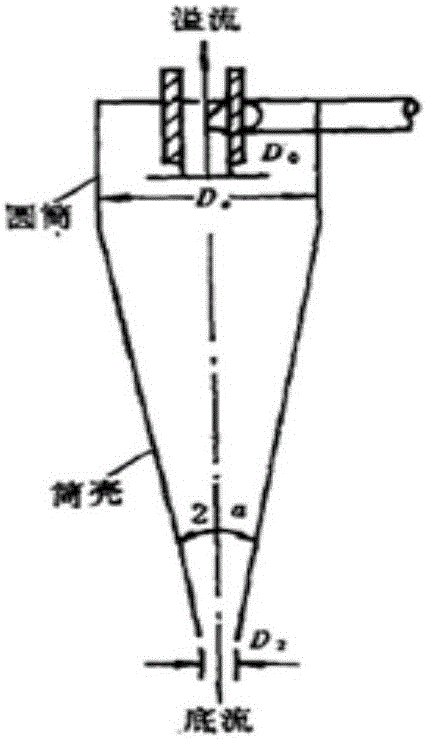

Image

  • Circulating cooling water bypass flow water treatment system and bypass flow water treatment method
  • Circulating cooling water bypass flow water treatment system and bypass flow water treatment method
  • Circulating cooling water bypass flow water treatment system and bypass flow water treatment method

Examples


Embodiment 1

[0189] Three side flow water treatment devices are installed in the cooling circulating water system in the form of side flow, and the circulating water volume is 2000m 3 / h, the reserved volume is 1500m 3 , using two sets of side flow water treatment devices, the total treatment capacity of the side flow water treatment devices is 75m 3 / h, 24-hour continuous operation, processing 1800m a day 3 , the water to be treated at a temperature of 15-40°C enters the reaction chamber from the inlet of the reaction chamber. The reaction chamber itself is the cathode of the electrolysis process, and the inside of the reaction chamber is provided with an anode. The anode is V-shaped, with a total width of The length is 50mm and the length is 800mm. There is a scraper between the cathode and the anode. The scraper motor starts the scraper according to the instructions given by the controller to scrape off the precipitated scale or deposited suspended solids and heavy metals on the surfac...

Embodiment 2

[0215] The first and second phases of the evaporative condenser bypass electrolytic water processor (ECT) in a food factory were installed in April 2014 and put into use in May of the same year. There are 8 evaporative condensers in the first and second phases, each of which is opened irregularly, with a total circulating water volume of 1,736m 3 / h. A total of 19 ammonia compressors are in service, each of which is turned on irregularly. Four ECTs are used, installed in the form of side flow, and run continuously for 24 hours. The water to be treated at a temperature of 15-40°C enters the reaction chamber from the inlet of the reaction chamber. The reaction chamber itself is the cathode of the electrolysis process, and the inside of the reaction chamber is provided with an anode. The anode is V-shaped and has a total width of 50mm, length 800mm, there is a scraper between the cathode and the anode, the scraper motor starts the scraper according to the instructions given by ...

Embodiment 3

[0257] In a new workshop of a food processing factory, the evaporative condenser side-flow electrolytic water processor (ECT electrolytic water processor) was installed at the end of May 2014 and put into use in July of the same year. There are 10 evaporative condensers in the first workshop, each of which is opened irregularly, with a total circulation of 1,363m 3 / h, a total of 31 compressors, each of which is turned on irregularly.

[0258] The circulating water treatment system of the workshop uses 3 sets of ECT equipment with a treatment capacity of 30m 3 / h; Since the equipment is installed in the refrigeration room, we choose a flow rate of 50m 3 / h, Yangcheng 15m circulating water pump; the water intake is at the sewage pipe of each evaporative cooling unit, and the DN50 pipe is connected to the main water inlet pipe of DN100, and a valve is installed at each sewage pipe to adjust the flow; The water treated by the ECT system is evenly distributed to each evaporative...


PUM


Abstract

The invention provides a circulating cooling water bypass flow water treatment system and a bypass flow water treatment method. The bypass flow water treatment system comprises a bypass flow water fetching unit, an electrochemical water treatment device connected with bypass flow water fetching unit, a cyclone hydraulic separator connected with the electrochemical water treatment device, and a sewage discharging unit connected with a sewage discharging port of a reaction chamber and a bottom flow port of the cyclone hydraulic separator, the electrochemical water treatment device comprises the reaction chamber, an anode arranged at the top end of the inside of the reaction chamber, a scraper positioned between the reaction chamber and the scraper and a driving device driving the scraper and positioned below the reaction chamber, and an overflow port of the cyclone hydraulic separator is connected with a circulating water system. The bypass flow water treatment system controls water quality to be within a proper range by controlling balance among water quantity, minerals, suspended matters and ecology, so that the problems of scaling, corrosion, the suspended matters and microorganisms in the circulating cooling water system are solved.

Description

technical field [0001] The invention relates to the field of circulating cooling water treatment, in particular to a circulating cooling water side flow water treatment system and a side flow water treatment method. Background technique [0002] The circulating cooling water system is a water supply system that uses water as the cooling medium and is composed of heat exchange equipment, cooling equipment, water pumps, pipelines and other related equipment, and is recycled. Bypass water is the part of water that is diverted from the circulating cooling water system and treated, and then returned to the circulating cooling water system. [0003] Circulating cooling water refers to exchanging heat through a heat exchanger or direct contact heat exchange to exchange heat from a medium, and after being cooled by a cooling tower, it is recycled to save water resources. In general, the circulating cooling water is neutral or weakly alkaline, and the pH value is controlled between ...

Claims


Application Information

Patent Timeline
IPC IPC(8): C02F9/06C02F103/02
CPCC02F1/38C02F1/4602C02F1/4672C02F9/00C02F2103/023C02F2303/04C02F2303/08C02F2305/023
Inventor 章明歅章俊杰
Owner 章明歅
Learn More