
Hard rail numerical control lathe

A technology of CNC lathes and hard rails, applied in the field of CNC lathes, can solve the problems of complex connection, small turning feed, high maintenance frequency, etc., and achieve the effect of avoiding unstable transmission, improving power and torque, and ensuring safety performance

Active Publication Date: 2016-08-03
GOODWAY MACHINE WUJIANG CORP
View PDF6 Cites 11 Cited by
  • Summary
  • Abstract
  • Description
  • Claims
  • Application Information

AI Technical Summary

Problems solved by technology

[0003] Disadvantages of the existing technology: the base structure of small and medium-sized CNC lathes is weak, and the turning feed rate is small, which cannot meet the client's needs for heavy cutting and large workpieces
The design of medium and light load line rails cannot meet the foundation of heavy cutting, and the long-term service wears a lot, and the maintenance frequency is high
The manual tailstock connection mode is inconvenient to adjust when changing different workpieces; the X-axis motor drives the tailstock with high cost and inconvenient maintenance
The water tank is built in the machine bed with low strength, limited space, and water circulation loop. The heat dissipation effect is not good, which affects its machining accuracy; the water tank is short and the chip accumulation is obvious, which affects the service life of the pump.
There is no detection system for abnormal lubrication in the mechanical lubrication system, and there are certain safety hazards
The outer cover has a lot of sheet metal and complex connection forms, and the space is small, making it difficult for maintenance personnel to enter the modification area for maintenance

Method used


Image

  • Hard rail numerical control lathe
  • Hard rail numerical control lathe
  • Hard rail numerical control lathe

Examples


Embodiment Construction

[0028] The implementation of the present invention will be illustrated by specific specific examples below, and those skilled in the art can easily understand other advantages and effects of the present invention from the contents disclosed in this specification.

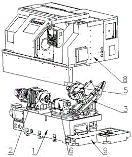
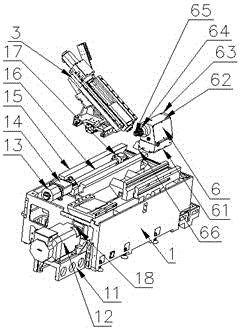
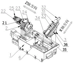
[0029] see Figure 1 to Figure 5 . It should be noted that the structures, proportions, sizes, etc. shown in the drawings attached to this specification are only used to match the content disclosed in the specification, for those who are familiar with this technology to understand and read, and are not used to limit the implementation of the present invention. Limiting conditions, so there is no technical substantive meaning, any modification of structure, change of proportional relationship or adjustment of size, without affecting the effect and purpose of the present invention, should still fall within the scope of the present invention. The disclosed technical content must be within the scope covered. At the sa...


PUM

PropertyMeasurementUnit
Diameteraaaaaaaaaa

Abstract

The invention provides a hard rail numerical control lathe. The hard rail numerical control lathe comprises a base module. The base module comprises a motor base, a spindle motor, a Z-axis motor, a Z-axis motor base, a base body, a Z-axis lead screw, a bearing block and a motor belt wheel. The spindle motor is fixed to the side edge of the base body through the motor base. The motor belt wheel is fixed to the spindle motor. The Z-axis motor base is fixed to the base body. One end of the Z-axis lead screw is connected with the Z-axis motor base, and the other end of the Z-axis lead screw is connected with the bearing block. The problems that when a traditional machine tool is used for machining a larger workpiece, the cutting strength of a spindle is insufficient, feed horsepower of all shafts is weak, the strength of a base is not high enough, and machining feed is excessively large, and consequently tool abrading, jamming, servo alarming and even burning-out of a spindle bearing are caused are solved, and the phenomenon of instable transmission caused by the fact that a certain part of a pipeline is not lubricated in place due to the long use cycle and the phenomenon of burning-out of a rail due to the fact that the rail makes contact with overheat are avoided.

Description

technical field [0001] The invention relates to a numerically controlled lathe. Background technique [0002] With the increasingly fierce competition in the market, clients are constantly putting forward new requirements for product quality and functions, and the production cycle of customer needs is getting shorter and shorter. Improving production efficiency, reducing defect rate, stabilizing production operations, shortening processing cycle, and improving enterprise competitiveness have become the development trend of enterprises. With the implementation of the enterprise occupational safety and health system, improving work safety is also one of the goals that the enterprise has been pursuing. The medium-sized CNC machine tools developed in the market are usually in the form of a built-in water tank in the base. Due to the high transmission speed of the spindle, the αP22i spindle system is usually equipped with an ordinary X-axis motor to drive the line-rail connect...

Claims


Application Information

Patent Timeline
IPC IPC(8): B23B21/00B23B19/02B23B23/04B23Q1/01B23Q11/08B23Q11/12
CPCB23B23/04B23Q1/015B23Q1/25B23Q1/70B23Q11/08B23Q11/122
Inventor 秦彬鼎许威凯
Owner GOODWAY MACHINE WUJIANG CORP
Learn More