Automatic feeding equipment

An automatic feeding and equipment technology, applied in the direction of conveyors, conveyor objects, mechanical conveyors, etc., can solve the problems of inaccurate positioning, insufficient flexibility, unstable driving and turning, etc., to achieve the effect of ensuring stability and saving space

Inactive Publication Date: 2016-08-03
SHENZHEN SCREEN STAR PRINTING MASCH CO LTD
View PDF7 Cites 9 Cited by
  • Summary
  • Abstract
  • Description
  • Claims
  • Application Information

AI Technical Summary

Problems solved by technology

[0003] The loading and unloading mechanisms integrated on the existing AGV trolley are both rolling mechanisms or sliding mechanisms, and the loading and unloading actions are completed by the rolling mechanism or sliding mechanism and the outside. However, due to the characteristics of these two mechanisms, in many cases It must be fixed and suspended on one side of the AGV trolley to realize its function, so that the center of gravity of the trolley is biased towards the cantilever side. The trolley needs to occupy a large aisle space around it during driving, and the driving and turning are unstable, which is very likely to hurt People or things around; at the same time, the two mechanisms are not flexible enough to realize multi-point placement on the same station, and cannot be positioned accurately. The materials that can be transported at a time are very limited, and it is impossible to realize a single mechanism to transport multi-frame materials at a time.

Method used


Image

  • Automatic feeding equipment
  • Automatic feeding equipment
  • Automatic feeding equipment

Examples


Embodiment Construction

[0031] In order to make the object, technical solution and advantages of the present invention clearer, the present invention will be further described in detail below in conjunction with the accompanying drawings and embodiments. It should be understood that the specific embodiments described here are only used to explain the present invention, not to limit the present invention.

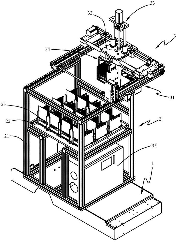
[0032] figure 1 A schematic diagram of the overall structure of an automatic feeding device according to an embodiment of the present invention is shown. Such as figure 1 As shown, the automatic feeding equipment is mainly composed of an AGV trolley 1, a storage device 2 and a loading and unloading device 3. The AGV trolley 1 can run along a prescribed guiding path for material delivery, which belongs to the prior art, so it will not be described in detail here. The material storage device 2 is installed on the AGV trolley 1 and mainly consists of a frame 21 , a tray 22 and a plurality of materi...


PUM


Abstract

The invention relates to an automatic feeding device, comprising an AGV trolley, a material storage device, and a loading and unloading device. A plurality of material frames are arranged on the pallet of the material storage device. The loading and unloading device includes a Y-axis multiplying stroke mechanism, an X-axis moving module, a Z-axis moving module, a reclaiming manipulator, and an industrial control unit. The Y-axis multiplying stroke mechanism includes two first guide rails fixed on the left and right sides of the feeding direction on the frame and extending along the Y-axis, two multiplying plates that can slide along the two first guide rails, and fixed on the two multiplying plates respectively. Two second guide rails on the board and extending along the Y axis, two fixed plates that can slide along the two second guide rails, and a stroke multiplication drive unit, the stroke multiplication drive unit drives the two multiplication plates to slide along the first guide rails respectively At the same time, the two fixing plates are driven to slide along the same direction along the second guide rail to realize the stroke multiplication. The invention can meet the requirements of automatic feeding, loading and unloading, and can realize multi-point placement on the same station, and at the same time occupies a small space and operates stably.

Description

technical field [0001] The present invention relates to mechanical equipment, more particularly, relates to a kind of automatic material feeding equipment. Background technique [0002] AGV trolley (Automated Guided Vehicle) is an automatic guided transport vehicle, which can drive along the prescribed guiding path, has safety protection and various transfer functions, so it has gradually been applied to various automated production lines for feeding and loading and unloading. [0003] The loading and unloading mechanisms integrated on the existing AGV trolley are both rolling mechanisms or sliding mechanisms, and the loading and unloading actions are completed by the rolling mechanism or sliding mechanism and the outside. However, due to the characteristics of these two mechanisms, in many cases It must be fixed and suspended on one side of the AGV trolley to realize its function, so that the center of gravity of the trolley is biased towards the cantilever side. The trolle...

Claims


Application Information

Patent Timeline
Patent Type & Authority Applications(China)
IPC IPC(8): B65G35/00B65G47/90
Inventor 尹国伟丘斯波何彩绒徐丽平
Owner SHENZHEN SCREEN STAR PRINTING MASCH CO LTD
Why Eureka
Try Eureka