Annular differential-mode inductor and production method thereof

A technology of differential mode inductors and production methods, which is applied in the field of magnetoelectricity, can solve the problems of reducing the service life of downstream products, increasing the magnetic core, and losing application performance, so as to improve the anti-electromagnetic interference performance, reduce the parasitic capacitance value, and product Apply performance-intensive effects

Inactive Publication Date: 2016-08-03
湖口健诚电子电器有限公司
View PDF7 Cites 8 Cited by
  • Summary
  • Abstract
  • Description
  • Claims
  • Application Information

AI Technical Summary

Problems solved by technology

Its main disadvantages are: the winding process is complicated and cumbersome, especially it is difficult to adapt to the winding of enameled copper wire with a large cross-sectional area, resulting in low production efficiency; Damage or pinholes appear, which reduces the yield; the product power is small, and it is difficult to meet customer requirements in case of downstream products that require a slightly larger current in the circuit; to solve such problems, one is to increase the magnetic The second is to increase the enamelled copper wire, but due to the limitation of the magnetic core space, it cannot be produced and does not meet the actual requirements; the magnetic core is easy to saturate, which will correspondingly lose the application performance and reduce the downstream product lifespan

Method used


Image

  • Annular differential-mode inductor and production method thereof
  • Annular differential-mode inductor and production method thereof
  • Annular differential-mode inductor and production method thereof

Examples


Embodiment Construction

[0028] Below in conjunction with accompanying drawing and embodiment the present invention is further described:

[0029] see Figure 1-Figure 4 .

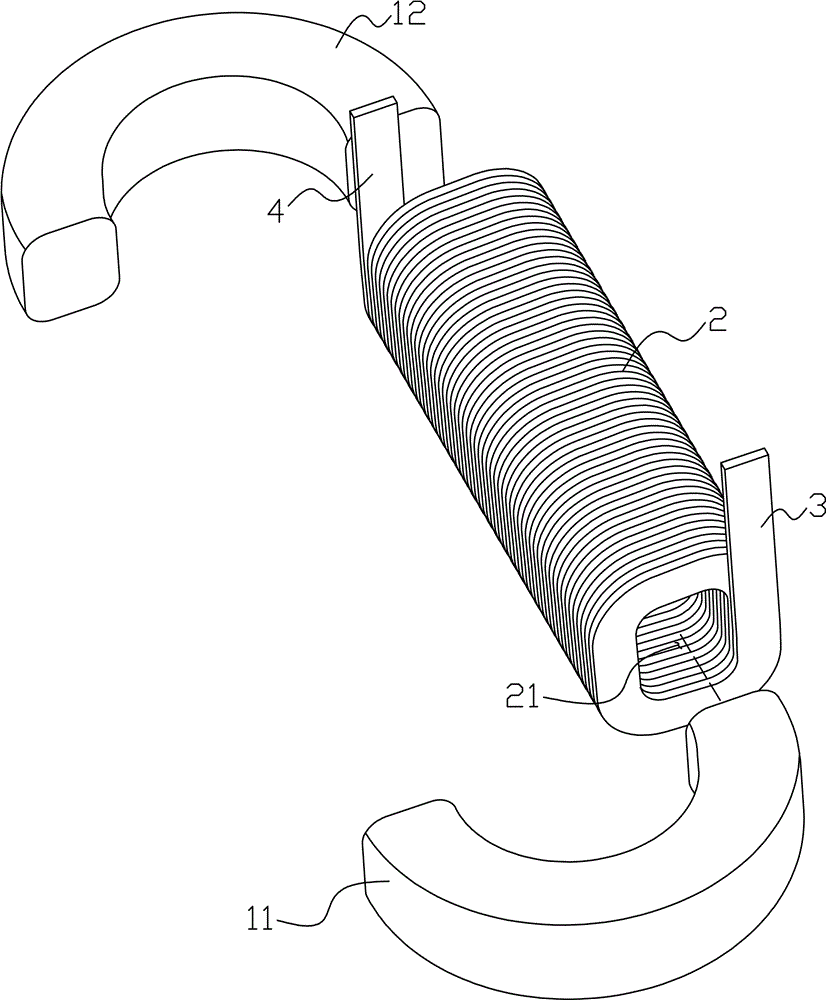
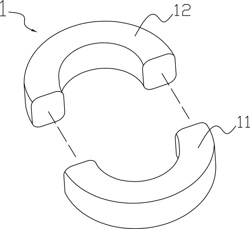
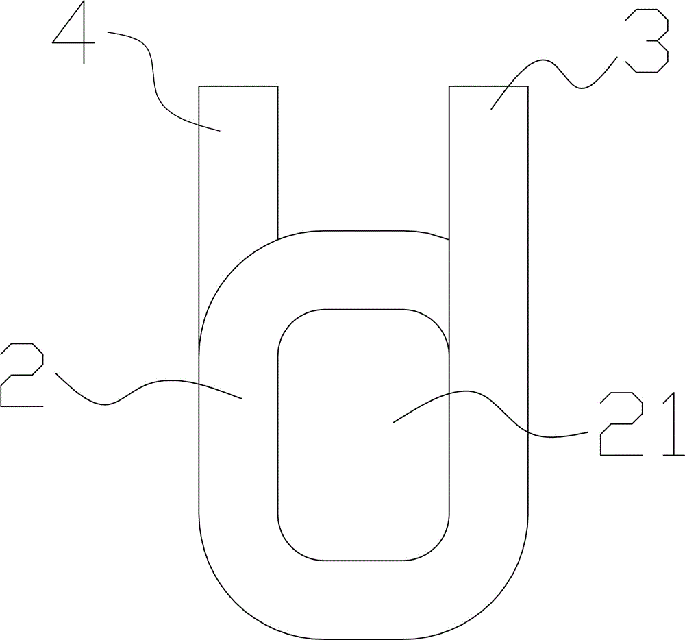
[0030] The invention discloses an annular differential mode inductor, which comprises an annular magnetic core 1 and a coil 2. The annular magnetic core 1 is formed by butting a first magnetic core 11 and a second magnetic core 12. The window 21 forms a magnetic core channel, and the first and second magnetic cores are inserted into the magnetic core channel and then docked. In this case, the coil 2 is wound in advance with a winding machine as required, and the annular differential mode inductor passes through the first and second The magnetic core is formed by butting after passing through the wound coil. The winding process is simple, which solves the problem that the wire diameter is too large and cannot be wound. At the same time, it reduces the labor intensity of the workers and improves the production efficiency; The copp...


PUM


Abstract

The present invention relates to the field of magnetoelectric technology, in particular to a ring-shaped differential-mode inductor and a production method thereof. The ring-shaped differential-mode inductor includes a ring-shaped magnetic core and a coil, and the ring-shaped magnetic core is connected by a first magnetic core and a second magnetic core. In combination, the window in the middle of each turn coil forms a magnetic core channel, and the first and second magnetic cores are inserted into the magnetic core channel and then docked. The production method of the annular differential mode inductor comprises the following steps: winding the coil by a winding machine, respectively passing the first and second magnetic cores through the coil, while the second magnetic core is passed through the other end of the coil core channel, and the The starting and tail wires are stripped and soldered. In the present invention, the coil passes through the magnetic core after being wound by a winding machine. The winding process is simple, which solves the problem that the wire diameter is too large and cannot be wound. At the same time, it reduces the labor intensity of workers and improves production efficiency; The copper wire will be damaged or have pinholes during the process, which improves the yield.

Description

technical field [0001] The invention relates to the field of magnetoelectric technology, in particular to an annular differential mode inductor and a production method thereof. Background technique [0002] Inductance is a property of a closed loop that when the current through the closed loop changes, an electromotive force appears to resist the change in current. Inductors have a blocking effect on alternating current. The differential mode inductor must flow through the AC power supply current. When the AC frequency is constant, the greater the inductance of the differential mode inductor, the greater the resistance to alternating current, and the smaller the inductance, the smaller the resistance. In addition, in the case of a certain inductance, the higher the frequency of the alternating current, the greater the resistance of the inductor to the alternating current, and the lower the frequency, the smaller the resistance of the inductor to the alternating current. In...

Claims


Application Information

Patent Timeline
Patent Type & Authority Applications(China)
IPC IPC(8): H01F17/06H01F27/28H01F27/24H01F41/08
CPCH01F17/062H01F27/24H01F27/2847H01F41/08
Inventor 张唐霞石小莲
Owner 湖口健诚电子电器有限公司
Why Eureka
Try Eureka