Device using hollow cathode to adjust ion energy

A hollow cathode and ion energy technology, which is applied in the field of ions, can solve the problems of affecting the discharge characteristics of the hollow cathode, increasing the input power of the hollow cathode, and the small adjustment range of the ion energy, and achieves low processing cost, extremely wide application range, and improved conversion efficiency. Effect

Inactive Publication Date: 2016-08-10
MATERIAL INST OF CHINA ACADEMY OF ENG PHYSICS
View PDF10 Cites 3 Cited by
  • Summary
  • Abstract
  • Description
  • Claims
  • Application Information

AI Technical Summary

Problems solved by technology

Since the sample is between the first cathode and the anode plate, the adjustment of the bias voltage is limited to the electric field distribution when the hollow cathode is discharged, and the conductive sample in the cathode cylinder can affect the discharge characteristics of the hollow cathode, making it very difficult to control the ion energy
[0004] The publication number is CN104827177A, and the title is "a low-voltage high-current electron beam vacuum welding device" which discloses a welding device in which the negative pole of the discharge power supply is connected to the hollow cathode, and the positive pole of the discharge power supply is connected to the accelerating electrode. This method It can only change the energy of electrons, and the acceleration power supply is equivalent to increasing the input power of the hollow cathode, and the effect on ion energy is not obvious
[0005] The publication numbers are CN102497721A, CN102376521A and other similar technical solutions, all of which utilize the hollow cathode discharge principle to enhance the beam current density of the plasma, but because the voltage drop of the hollow cathode is mainly concentrated inside the cathode tube, the adjustment range of ion energy is very large. Small

Method used


Image

  • Device using hollow cathode to adjust ion energy

Examples


Embodiment

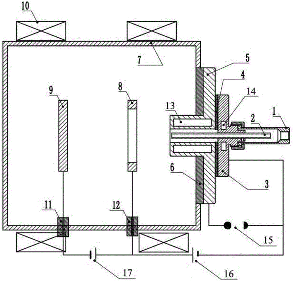
[0033] Such as figure 1 As shown, the present invention provides a plasma generating device for material modification and material interaction mechanism in a linear strong magnetic field device, which can generate a plasma beam with a high ionization rate. The invention includes a sealed tube, a hollow cathode tube 2, a cathode plate 3, a connecting plate 4, an auxiliary anode plate 5, a vacuum chamber 7, an annular anode plate 8, a sample holder 9, a magnetic field coil 10 and a control power supply. The hollow cathode tube 2 is mounted on the cathode plate 3, which can be a tantalum tube or a tantalum alloy tube, and is locked on the central axis of the cathode plate 3 by screws. The sealed tube is connected to the cathode plate 3, and the hollow cathode tube 2 is inserted into it to realize the sealing of the hollow cathode tube. The top of the sealed tube is also provided with a gas (such as Ar, He, N2, H2, etc.). Kind of gas) is input to the gas inlet 1 in the hollow cath...


PUM


Abstract

The invention discloses a device using a hollow cathode to adjust ion energy. The device comprises a sealing tube, a hollow cathode tube, a cathode plate, a connection plate, an auxiliary anode plate, a vacuum chamber, a ring-shaped anode plate, a sample placing frame, a magnetic field coil and a control power supply. The hollow cathode tube is arranged on the cathode plate. The sealing tube is connected with the cathode plate. The hollow cathode tube is sleeved into the sealing tube. A gas inlet is arranged in the top of the sealing tube. An insulating partition plate is arranged on the auxiliary anode plate. Through the connection plate, potential difference is formed between the cathode plate and the auxiliary anode plate. The ring-shaped anode plate and the sample placing frame are located in the vacuum chamber. The vacuum chamber is connected with the insulating partition plate. The magnetic field coil wraps the vacuum chamber. The control power supply is connected with the cathode plate, the auxiliary anode plate, the ring-shaped anode plate and the sample placing frame. The device provided by the invention has the advantages of easy ion energy control, obvious effect and wide adjustment range, and can satisfy the application of industry and scientific research.

Description

Technical field [0001] The invention relates to the technical field of low-temperature plasma, in particular to a device for adjusting ion energy by using a hollow cathode. Background technique [0002] At present, in the field of industrial and scientific research applications, the control of plasma parameters, such as electrons, ion density, and energy, in low-temperature plasma applications, is essential for optimizing the process and expanding the application range. [0003] The publication number is CN1904134 and the name is "hollow cathode ion metalizing device". It discloses a cathode cylinder equipped with metal to be infiltrated, and a DC bias voltage is added between the flat anode and the sample workpiece, and the bias voltage is used to change the incident to the sample. Ion energy. Since the sample is located between the first cathode and the anode plate, the adjustment of the bias voltage is limited to the electric field distribution of the hollow cathode during disc...

Claims


Application Information

Patent Timeline
Patent Type & Authority Applications(China)
IPC IPC(8): H05H1/24
CPCH05H1/24
Inventor 金伟芶富均徐海燕王东平梁传辉刘柯钊阿尔特·威廉姆·柯莱恩
Owner MATERIAL INST OF CHINA ACADEMY OF ENG PHYSICS
Why Eureka
Try Eureka