Technical method for large curved-surface composite material tool overall detection

A technology of composite materials and process methods, which is applied in the field of overall inspection of large-scale curved surface composite material tooling, and can solve problems such as misjudgment, a large number of auxiliary man-hours, and easy distortion of inspection data.

Active Publication Date: 2016-08-17
SHENYANG AIRCRAFT CORP
View PDF9 Cites 0 Cited by
  • Summary
  • Abstract
  • Description
  • Claims
  • Application Information

AI Technical Summary

Problems solved by technology

[0004] 1) The deformation state of the tooling is judged by comparing the gap between the contact surface and the level difference between different templates through the large-scale cut surface template stuck in the tooling surface. When the curvature of the tooling changes greatly, it mainly depends on a number of experienced operators. It is completed in cooperation with each other, and it is difficult for workers to operate, the workload is heavy, and there is a large detection error;
[0005] 2) The optical non-contact measurement process is cumbersome, and there are many auxiliary man-hours in the early stage, especially when the surface roughness of the tooling after rough machining is large, and when the surface of the tooling changes greatly, the accuracy of the data obtained by optical scanning and photography is not very good. When manually processing the collected point cloud data through computer software, it is ...

Method used


Image

  • Technical method for large curved-surface composite material tool overall detection
  • Technical method for large curved-surface composite material tool overall detection

Examples


Embodiment Construction

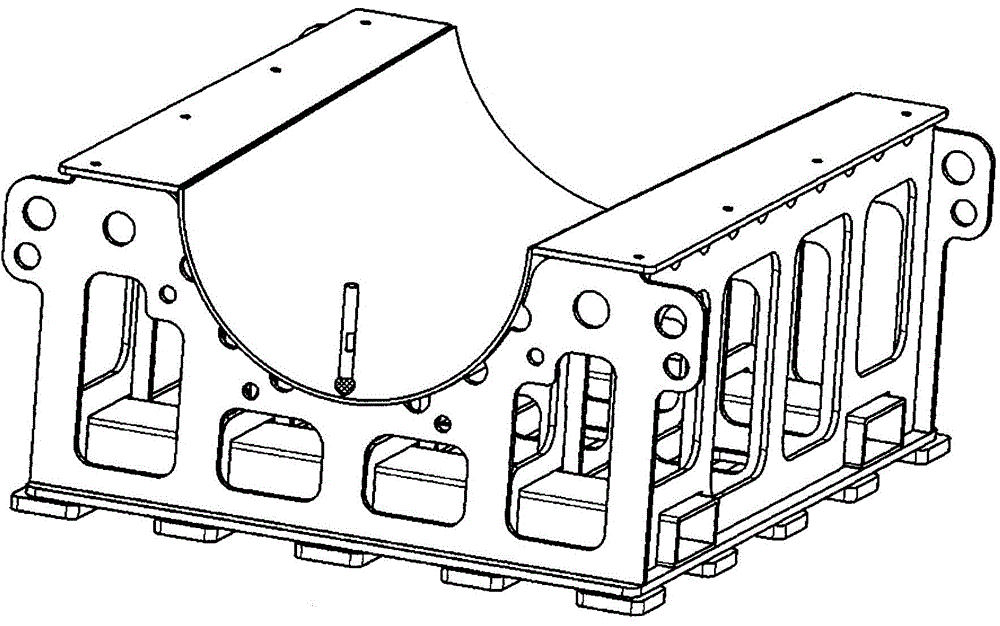
[0025] A process method for the overall detection of a large-scale curved surface composite material tooling, comprising the following steps:

[0026] 1) After the tooling is finished with CNC rough machining or semi-finishing, perform vibration relief operation;

[0027] 2) Remove grease, waste liquid and impurities on the surface of the tooling, and keep the surface of the tooling clean and clean;

[0028] 3) Spray the optical measurement developer evenly on the tooling surface to ensure uniform coverage and consistent thickness;

[0029] 4) Put the tooling back on the original CNC machine tool in a natural state, and ensure the original processing station;

[0030] 5) Use thin gaskets to fill up the vacant space on the bottom surface of the deformed tooling, and press the pressure plate to ensure that the bottom surface of the tooling is flat;

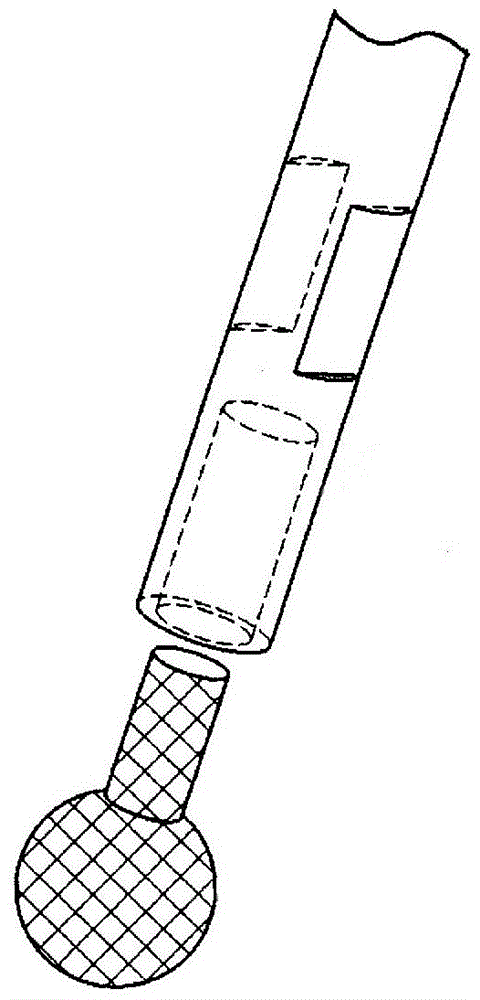
[0031] 6) Nylon ball head with handle is cured by high-elastic nylon wire, such as figure 1 The diameter of the ball shown is 4...


PUM


Abstract

The invention relates to a technical method for large curved-surface composite material tool overall detection. A nylon bulb and a cylindrical steel handle are assembled into a whole by means of a shanked bulb and are clamped to a cutter clamping handle of a numerical control machine tool; if contact deformation is generated between the bulb and a detected surface of a tool, the nylon bulb rubs a developing agent on the surface of the tool in a milling mode to form parallel marks, and the deformation tendency of the tool is judged according to width changes of the marks; the actual deformation amount of the tool is calculated according to z-axis adjustment amount, width difference, normal vectors and other parameters of the numerical control machine tool; according to the deformation amount and the tendency of the tool, a machining solution of a next procedure is formulated. The technical method improves detection efficiency of the tool in the machining process, a lot of subsidiary time is reduced, production cost can be greatly reduced, manufacturing efficiency and machining quality of the tool are improved, and labor intensity of operators and hoisting and overturning risks of a large tool are reduced.

Description

technical field [0001] The invention relates to a process method for the overall detection of a large-scale curved surface composite material tooling, which is used for the rapid detection of the tooling during the numerical control machining process of the tooling, and belongs to the field of mechanical manufacturing. Background technique [0002] In order to improve the stability of aviation large-scale composite material tooling, designers have increased the tolerance requirements for the thickness of the tooling's formed steel plate. Because the supporting base of the tooling and the connection with the formed steel plate are all welded, although the stress relief operation has been performed on the tooling, there is still the problem of secondary release of the remaining welding stress during the CNC machining process, and there is also the generation of processing stress . Under the combined action of the two, the tooling often deforms in different degrees and trends ...

Claims


Application Information

Patent Timeline
IPC IPC(8): B23Q17/00
CPCB23Q17/00B23Q17/007
Inventor 景智王佳宁许学军
Owner SHENYANG AIRCRAFT CORP
Why Eureka
Try Eureka