A Manipulator System with High Controllability

A manipulator, highly advanced technology, applied in the field of manipulator system, achieves the effects of novel structure, simple structure and lightening the weight of the pump

Active Publication Date: 2017-12-26
中山特云智慧控制技术研究有限公司
View PDF7 Cites 0 Cited by
  • Summary
  • Abstract
  • Description
  • Claims
  • Application Information

AI Technical Summary

Problems solved by technology

Users have higher and higher requirements on the speed, precision, cost, structure and other factors of handling robots. However, the existing handling robots can no longer meet many of people's requirements.

Method used


Image

  • A Manipulator System with High Controllability
  • A Manipulator System with High Controllability
  • A Manipulator System with High Controllability

Examples


Embodiment 1

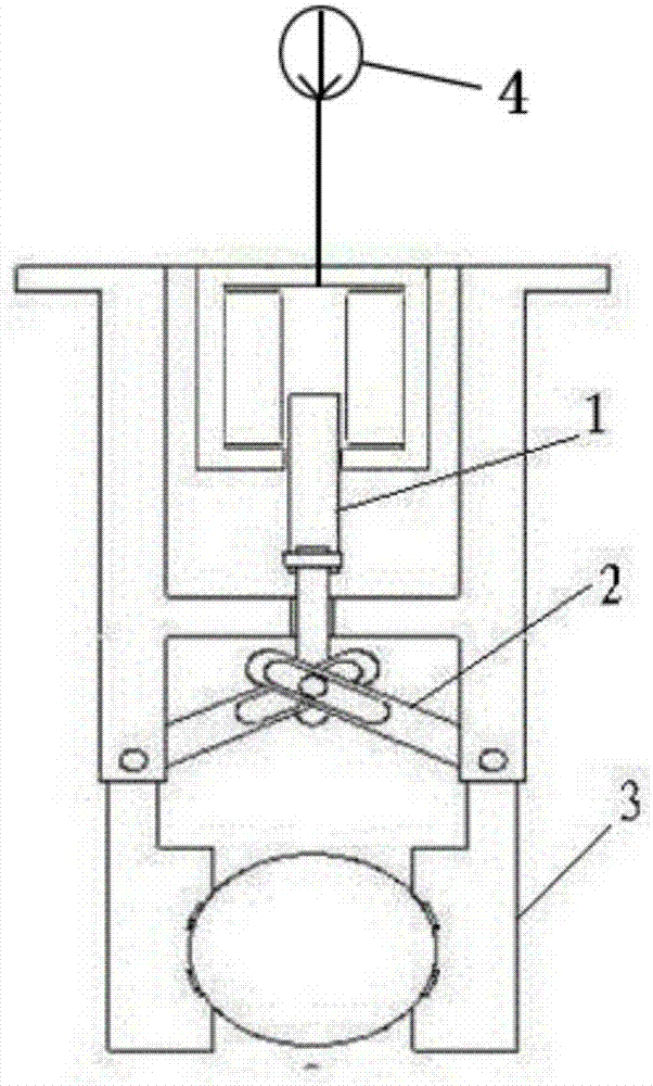
[0031] Such as figure 1 A manipulator system with a high degree of controllability is shown, including a driving part 1, a transmission part 2 and a finger part 3, the driving part 1 is connected through the transmission part 2 and drives the finger part 3, and the driving part 1 It is a hydraulic cylinder, and the finger part 3 includes at least two gripping mechanical fingers; the hydraulic cylinder is supplied with oil by an oil supply pump; the oil supply pump is a giant magnetostrictive pump 4 . The transmission part 2 is two mutually hinged plates. The two transmission parts 2 are provided with slide grooves. The end of the driving part 1 is connected with two transmission parts 2 at the same point. The transmission part 2 is two mutually hinged plates. The two transmission parts 2 are provided with slide grooves. The end of the driving part 1 is connected with two transmission parts 2 at the same point.

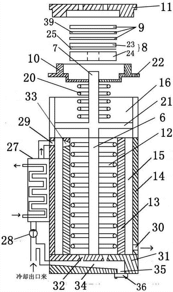
[0032] Such as figure 2 As shown, the giant magnetostricti...

Embodiment 2

[0042] Such as figure 1 A manipulator system with a high degree of controllability is shown, including a driving part 1, a transmission part 2 and a finger part 3, the driving part 1 is connected through the transmission part 2 and drives the finger part 3, and the driving part 1 It is a hydraulic cylinder, and the finger part 3 includes at least two gripping mechanical fingers; the hydraulic cylinder is supplied with oil by an oil supply pump; the oil supply pump is a giant magnetostrictive pump 4 . The transmission part 2 is two mutually hinged plates. The two transmission parts 2 are provided with slide grooves. The end of the driving part 1 is connected with two transmission parts 2 at the same point.

[0043] Such as figure 2 As shown, the giant magnetostrictive pump 4 is installed vertically as a whole, including a pump body, a giant magnetostrictive rod 6, an output shaft 7, a piston assembly 8, a one-way valve assembly 9, a pressure member 10, an end cover 11, and ...

Embodiment 3

[0053] Such as figure 1 A manipulator system with a high degree of controllability is shown, including a driving part 1, a transmission part 2 and a finger part 3, the driving part 1 is connected through the transmission part 2 and drives the finger part 3, and the driving part 1 It is a hydraulic cylinder, and the finger part 3 includes at least two gripping mechanical fingers; the hydraulic cylinder is supplied with oil by an oil supply pump; the oil supply pump is a giant magnetostrictive pump 4 . The transmission part 2 is two mutually hinged plates. The two transmission parts 2 are provided with slide grooves. The end of the driving part 1 is connected with two transmission parts 2 at the same point.

[0054] Such as figure 2 As shown, the giant magnetostrictive pump 4 is installed vertically as a whole, including a pump body, a giant magnetostrictive rod 6, an output shaft 7, a piston assembly 8, a one-way valve assembly 9, a pressure member 10, an end cover 11, and ...


PUM


Abstract

The invention discloses a manipulator system with the high controllability. The manipulator system comprises a driving part, a transmission part and a finger part; the driving part is connected with and drives the finger part through the transmission part, a hydraulic cylinder is adopted as the driving part, and the finger part comprises at least two externally-grasping mechanical fingers; oil is supplied to the hydraulic cylinder through an oil supply pump. The manipulator system is simple in structure, adopts the externally-grasping fingers as mechanical grippers for carrying a robot, is novel in structure, convenient to user and practical, can precisely control the oil supply pressure to control movement of the mechanical grippers and has the advantages of being good in heat dissipation condition, long in operation cycle, convenient to maintain and the like.

Description

technical field [0001] The invention relates to the field of manipulators, in particular to a highly controllable manipulator system. Background technique [0002] With the rapid development of modern science and technology and the progress of society, robot systems are more and more widely used in various fields. At present, the application fields of industrial robots mainly include arc welding, spot welding, assembly, handling, painting, testing, grinding and polishing, laser processing, etc. Among them, handling robots are widely used in handling work. Users have higher and higher requirements on the speed, precision, cost, structure and other factors of handling robots. However, the existing handling robots can no longer meet many of people's requirements. [0003] Under the excitation of an external magnetic field, the length and volume of ferromagnetic crystals will change, and when the external magnetic field excitation is removed, the size will return to the origina...

Claims


Application Information

Patent Timeline
Patent Type & Authority Patents(China)
IPC IPC(8): B25J9/08B25J15/08F04B17/00F04B53/00F04B53/08F04B53/10F04B53/14F04B53/16
CPCB25J9/08B25J15/08F04B17/00F04B53/00F04B53/08F04B53/102F04B53/108F04B53/14F04B53/143F04B53/16
Inventor 林守金
Owner 中山特云智慧控制技术研究有限公司
Why Eureka
Try Eureka