Quenching heat exchanger

A technology for quenching heat exchangers and heat exchangers, which is applied in the types of heat exchangers, direct contact heat exchangers, water shower coolers, etc. requirements and other issues, to achieve the effect of accelerating the flow rate of flue gas, the best effect, and strengthening the disturbance

Inactive Publication Date: 2016-08-17
杨丙
View PDF7 Cites 0 Cited by
  • Summary
  • Abstract
  • Description
  • Claims
  • Application Information

AI Technical Summary

Problems solved by technology

However, for hazardous waste incineration systems where the content of halogen elements in the waste is greater than 5% or the flue gas is small, the waste heat recovery device cannot be used to recover heat, and the high-temperature flue gas after incineration at 1100°C cannot be directly cooled to below 200°C. The device structure cannot meet the process requirements

Method used


Image

  • Quenching heat exchanger
  • Quenching heat exchanger
  • Quenching heat exchanger

Examples


Embodiment Construction

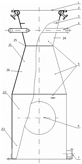
[0044] figure 1 An overall cutaway view of the quench heat exchanger is shown. like figure 1 As shown, the quench heat exchanger includes a shell 5, and the shell 5 includes a tapering section 24 and a diverging section 26, and the converging section 24 and the diverging section 26 are connected by a throat section 25; The tapered section 24 enters, first passes through the tapered section 24 and then passes through the tapered section 26 , and a chilling ring 2 is set at the position of the flue gas inlet 1 of the tapered section 24 .

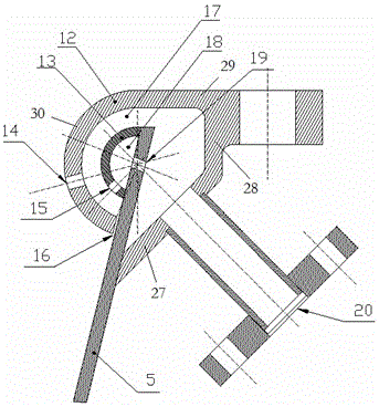
[0045] like figure 2 As shown, the quenching ring 2 is a hollow ring structure. The quenching ring 2 includes an inner ring chamber 18 and an outer ring chamber 17, and the housing 5 is inserted into the quenching ring 2, as figure 2 As shown, the quench ring 2 includes an outer shell 12 and an inner partition 13 . The inner partition 13 and the casing 5 form an inner chamber 18 , and the cavity formed by the inner partition 13 , the qu...


PUM


Abstract

The invention provides a quenching heat exchanger for cooling flue gas. The quenching heat exchanger comprises a shell, a quenching ring, a water retaining ring plate and a secondary quenching device, wherein the quenching ring, the water retaining ring plate and the secondary quenching device are arranged in the shell; the flue gas enters from an inlet of the heat exchanger, and sequentially passes through the quenching ring, the water retaining ring plate and the secondary quenching device; a plurality of spray holes are arranged in the quenching ring; and the distribution density of the spray holes is reduced upwards from a quenching ring gap. According to the quenching heat exchanger provided by the invention, the optimal effect of heat exchange is realized through arrangement of up-down hole diameters of the spray holes.

Description

technical field [0001] The invention belongs to the field of heat exchangers, in particular to a Venturi quench heat exchanger in which flue gas and water directly contact and exchange heat. The invention is mainly applied to the incineration system of hazardous waste containing halogen elements. Background technique [0002] With the development of the chemical industry, the production capacity of chemical products containing halogen elements has been greatly enlarged, and environmental protection issues have become increasingly prominent. The waste gas and waste liquid generated during the production process contain a large amount of organic compounds with extremely active halogen elements. Incineration of this type of waste must ensure that the dioxins in the purified flue gas meet the national environmental protection emission standards. A quenching device will be installed in the process to prevent the regeneration of dioxins. Usually, the regeneration temperature range...

Claims


Application Information

Patent Timeline
Patent Type & Authority Applications(China)
IPC IPC(8): F28C3/08
CPCB01D47/06B01D53/40B01D53/78F23J15/02F23J15/022F23J15/06F28C3/08F28F13/12F28F25/06Y02E20/30
Inventor 朱峰
Owner 杨丙
Why Eureka
Try Eureka