
Monolithic integration depolarized fiber optic gyroscope optical chip

A fiber optic gyroscope and optical chip technology, applied in the field of integrated optics and inertial sensing, can solve the problems of poor reliability of the coupling point fusion point, small half-wave voltage, large modulation bandwidth, etc., and achieve simple structure, low-loss butt coupling, waveguide simple structure

Inactive Publication Date: 2016-08-17
ZHEJIANG UNIV
View PDF7 Cites 9 Cited by
  • Summary
  • Abstract
  • Description
  • Claims
  • Application Information

AI Technical Summary

Problems solved by technology

[0004] The integrated optical chip widely used in the depolarized fiber optic gyroscope system is based on the L i NbO 3 integrated chip of bulk material, L i NbO 3 The electro-optical phase modulator has the characteristics of low insertion loss, small half-wave voltage, and wide modulation bandwidth. It is an ideal device for closed-loop work, but the L i NbO 3 Bulk material waveguides are not easy to achieve monolithic integration with other material waveguides, and need to be connected to other optical devices through fiber coupling; the Lyot depolarizer used is two high-birefringence polarization-maintaining optical fibers with a length ratio of 1:2. The main axis is 45° It is made by welding, each optical device is separated, the structure is complex, and the reliability of the welding point of the coupling point is poor, which cannot meet the growing needs of the system's small and highly integrated technology

Method used


Image

  • Monolithic integration depolarized fiber optic gyroscope optical chip
  • Monolithic integration depolarized fiber optic gyroscope optical chip
  • Monolithic integration depolarized fiber optic gyroscope optical chip

Examples


Embodiment Construction

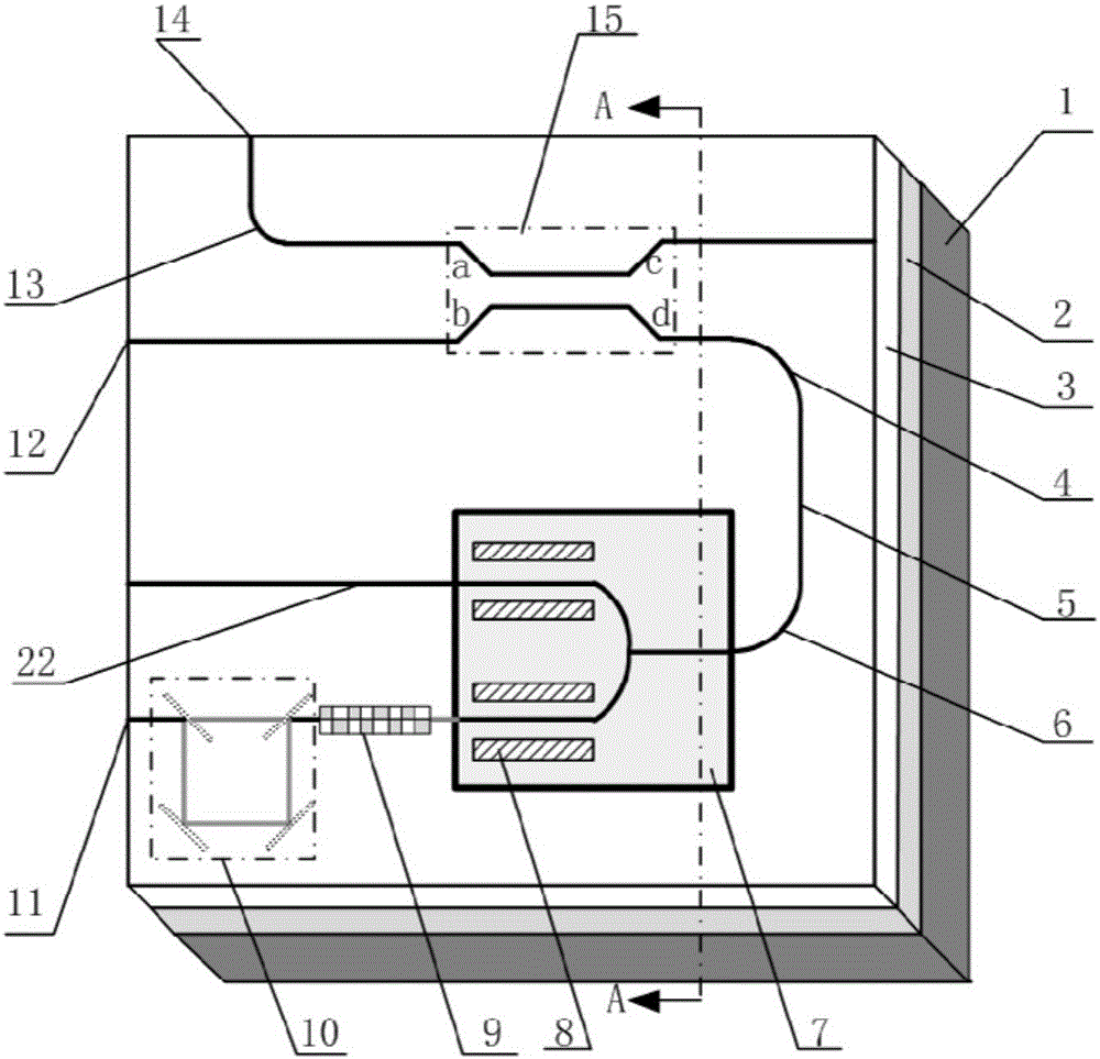
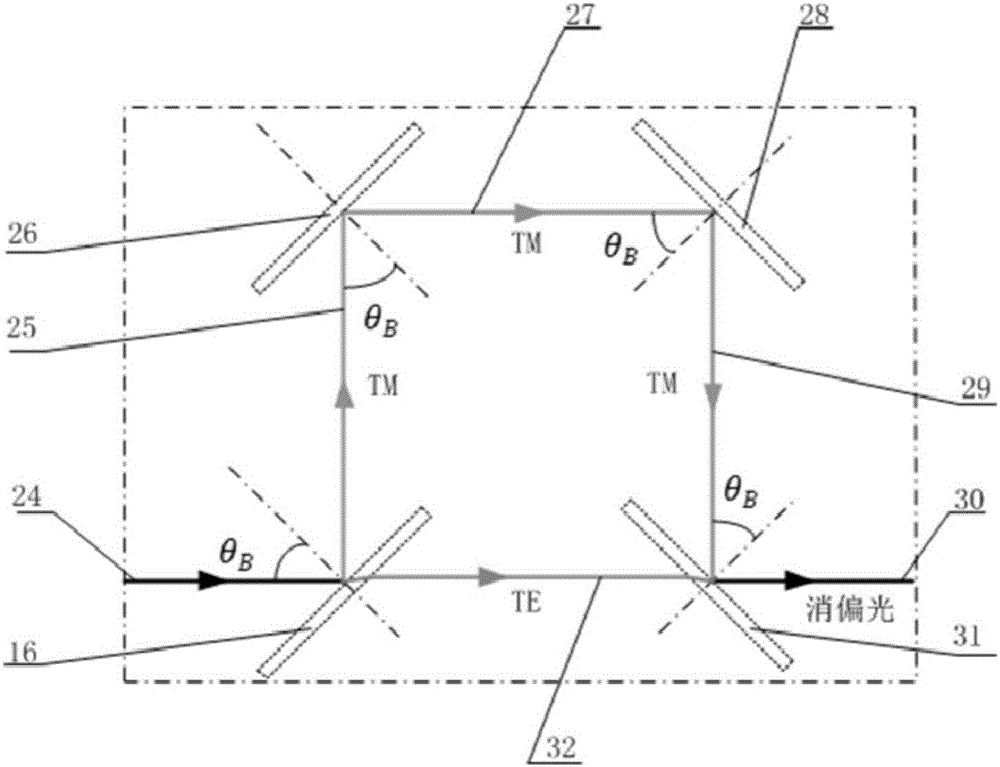
[0027] The present invention will be further described below in conjunction with accompanying drawing.

[0028] In this example, the chip substrate 1 material is Si, and the chip lower cladding layer 2 material is SiO 2 , the waveguide core layer 3 material is Si;

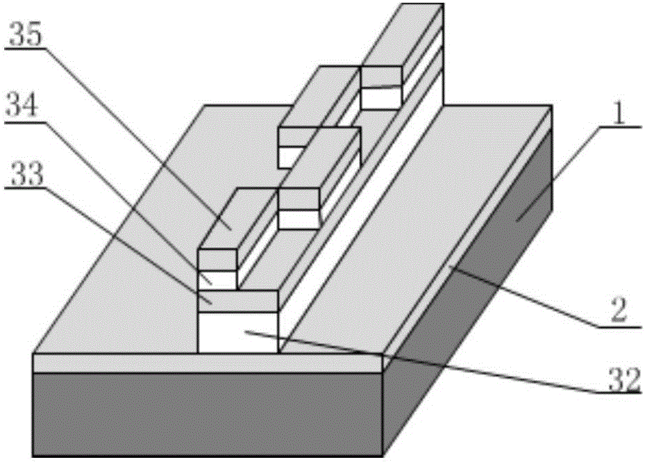
[0029] Such as figure 1 As shown, the waveguide core layer 3 integrates a directional coupler 15, a Y-waveguide modulator 7, a waveguide-type polarization converter 9, and a waveguide-type depolarizer 10, wherein the material of the Y-waveguide modulator 7 is thin-film lithium niobate 21, such as Figure 4 As shown, the light-passing area 23 of the waveguide modulator 7 is a thin-film lithium niobate proton exchange waveguide, and the core layer materials of other devices are all Si waveguides, and the shape of the waveguide is a Si ridge waveguide.

[0030] Port a of the directional coupler 15 is connected to one end of the first 90° arc waveguide 13 through the first straight waveguide, the other end of the fir...


PUM


Abstract

The present invention discloses a monolithic integration depolarized fiber optic gyroscope optical chip. The overall structure comprises a chip substrate, a chip lower cladding layer, and a waveguide core layer. The waveguide core layer is integrated with a directional coupler, a Y waveguide modulator, a waveguide type polarization converter and a waveguide type depolarizer. Light through the directional coupler achieves 3dB beam split; part of the light directly emits out of the chip, and the other part of the light enters the Y waveguide modulator to become high partial TE light; the high partial light is converted by a waveguide type TE polarization converter to become 45 DEG linearly polarized light; and polarized light passes through a depolarizer tp become completely depolarized light; and finally the completely depolarized light passes through a pigtail coupling port and enters into a single mode fiber ring. The optical chip of the present invention is highly integrated; the directional coupler, Y waveguide modulator and waveguide type depolarizer share the common substrate and the lower cladding layer. Except the core material of the Y waveguide modulator being a lithium niobate film, the core materials of the other waveguide devices are the same. The production process is simple, and the chip has better reliability and environmental adaptability.

Description

technical field [0001] The invention belongs to the technical field of integrated optics and inertial sensing, in particular to a depolarized optical fiber gyro optical chip integrated with a single substrate, that is, a monolithic chip. Background technique [0002] With the development of inertial technology, the volume and weight of the inertial system in the application field are getting higher and higher, and the design of an integrated, miniaturized, low-cost and high-stability fiber optic gyroscope becomes inevitable. [0003] Compared with the depolarization fiber optic gyroscope, the polarization maintaining fiber optic gyroscope has many advantages. In its structural design, the fiber ring adopts high birefringence polarization maintaining fiber, which avoids the signal attenuation caused by the polarization evolution in the single-mode fiber, and reduces the Faraday magnetic field effect and Polarization errors, but due to the high cost of polarization-maintaining...

Claims


Application Information

Patent Timeline
Patent Type & Authority Applications(China)
IPC IPC(8): G01C19/72
CPCG01C19/721
Inventor 佘玄李贝段启航李珂刘承舒晓武
Owner ZHEJIANG UNIV
Learn More