Refractive index measurement method with wide range

A refractive index and large-range technology, applied in the field of precision analysis and measuring instruments, can solve problems such as unfavorable real-time, online applications, limited measurement accuracy, unfavorable accurate measurement, etc.

Inactive Publication Date: 2016-08-24
SHANGHAI OPTICAL LITHOGRAPHY ENG
View PDF8 Cites 13 Cited by
  • Summary
  • Abstract
  • Description
  • Claims
  • Application Information

AI Technical Summary

Problems solved by technology

This method is powerless for the measurement of samples with high refractive index (n>1.7), and the measurement accuracy is limited
(2) Use the minimum deflection angle method of the spectrometer. Although this method has a certain measurement accuracy, the requirements for the sample to be tested are also high. In addition to processing the sample into a prism, it also requires a higher processing accuracy for the sample prism. requirements, usually limited to the measurement of transparent solid materials
(3) Michelson interferometer isoclinic interferometry, which is used for the measurement of refractive index, is limited to thin transparent bodies, and during the measurement process, the measurement time is too long because the sample to be measured and the measurement optical path need to be adjusted repeatedly , which is not conducive to real-time and online application

Method used


Image

  • Refractive index measurement method with wide range
  • Refractive index measurement method with wide range
  • Refractive index measurement method with wide range

Examples


Embodiment 1

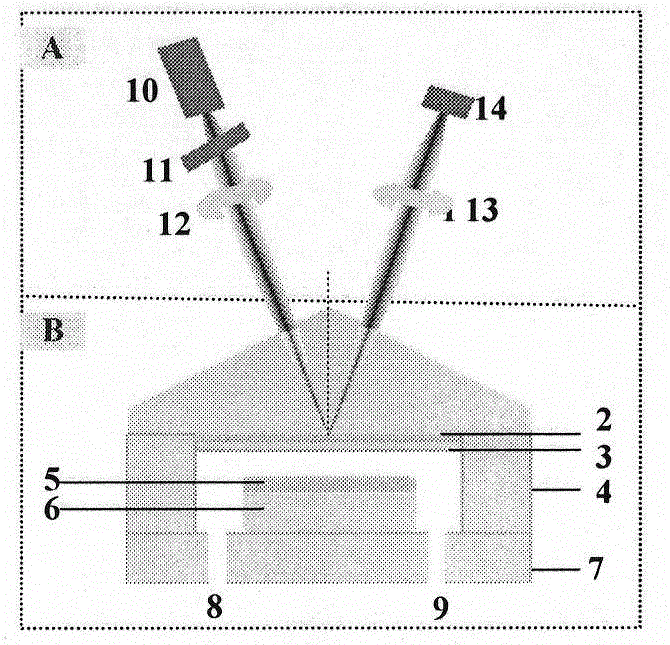
[0015] Assuming that the wavelength of the incident laser light λ = 650nm, the refractive index n of the glass prism 1 =1.80, the dielectric coefficient ε of the upper metal film 2 =-14.0+i1.3, thickness h 2 =45nm, the refractive index n of the silicon dioxide protective layer 3 =1.50, thickness h 3 =60nm, the dielectric coefficient ε of the lower metal film 5 =ε 2 =-14.0+i1.3, thickness h 5 =200nm (these parameters are accurately measured during the preparation process), the thickness of the glass island 6 is less than the glass gasket 4, the difference between the two h analyte = h 4 -h 6 =20 μm (the exact value can be determined by measurement and simulation calculation). Assuming that the sample cavity is filled with a gas with a low refractive index (nm = 15 °, the laser beam is a TM wave after passing through the polarizer 11, and the angular width Δθ=18 °-12 °=6 ° after being converged by the lens 13, then 5 black lines will appear in the reflected beam (refract...

Embodiment 2

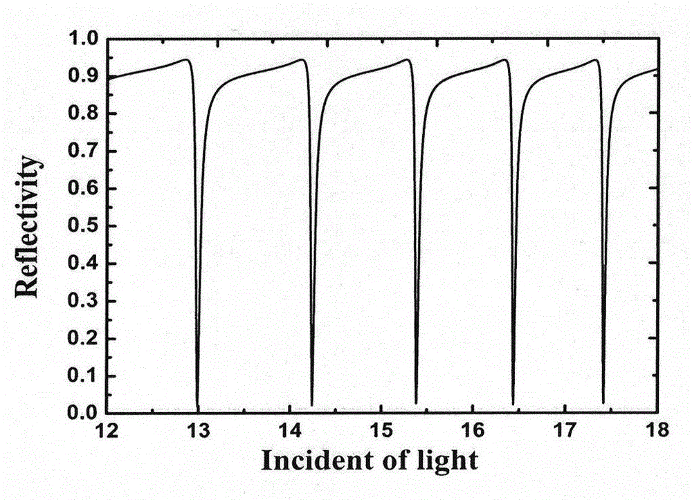
[0021] Assuming that the sample cavity is filled with an aqueous solution of a material (n>1.33), and other parameters remain unchanged, it is found that 4 black lines appear in the reflected beam, indicating that there are 4 angles in this angular width that satisfy the matching of the guided mode Conditions, by measuring the position of the black line on the CCD, four matching angles are obtained: θ m+1 =12.582°, θ m =14.328°, θ m-1 =15.881°, θ m-2 = 17.288°. Using the reflectivity formula to simulate and calculate the following parameters:

[0022] (1) The module sequence number m=80, therefore, the module sequence numbers of the four modules excited are 78, 79, 80 and 81 respectively;

[0023] (2) The thickness of the sample cavity is h analyte = 19.570 μm;

[0024] (3) The refractive index of the sample is n analyte = 1.40890.

[0025] The reflectivity curve simulated by computer is as image 3 Shown:

Embodiment 3

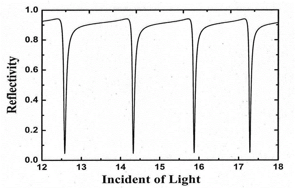
[0027]Assuming that what is filled into the sample cavity is a polymer colloid solution with a high refractive index (greater than that of the prism), and other parameters remain unchanged, it is found that 3 black lines appear in the reflected beam, indicating that there are 3 black lines in this angular width. The three angles meet the matching conditions of the guided mode. By measuring the position of the black line on the CCD, three matching angles are obtained: θ m+1 =12.647°, θ m =15.091°, θ m-1 = 17.202°. Using the reflectivity formula to simulate and calculate the following parameters:

[0028] (1) The modulus number m=117, therefore, the modulus numbers of the three modes excited are 116, 117 and 118 respectively;

[0029] (2) The thickness of the sample cavity is h analyte = 19.590 μm;

[0030] (3) The refractive index of the sample is n analyte = 1.98746.

[0031] The reflectivity curve simulated by computer is as Figure 4 Shown:


PUM

PropertyMeasurementUnit
Top angleaaaaaaaaaa
Thicknessaaaaaaaaaa
Thicknessaaaaaaaaaa

Abstract

The invention provides a refractive index measurement method with a wide range, and belongs to the field of physical measurement. Compared with the traditional measurement method which employs a total reflection principle, an angle of minimum deviation, and a Michelson interferometer, an apparatus uses a prism coupled symmetrical metal coated waveguide resonance structure. A sample to be measured is not positioned in an evanescent field, but in an oscillating field area-waveguide core layer. The arrangement expands the measurement range of refractive indices of samples, and effectively improves measurement sensitivity. The method is advantageous in that: (1) metal films are used as upper and lower coating layers of waveguide, the sample is used as a wave guiding layer, and the refractive index measurement range is not limited; (2) the sample can be liquid and gas; (3) the thickness of a waveguide hollow chamber is in a scale of dozens of micrometers, small-angle incident light can be used for exciting a higher-order guide mode with high sensitivity, wide-angle incident light can be used for exciting a surface plasma mode, an absolute value of the refractive index of sample can be accurately determined; (4) the higher-order guide mode with high sensitivity can be used as a probe, and the measurement precision reaches 0.00001.

Description

technical field [0001] The invention relates to a method for measuring the refractive index, in particular to a large-range refractive index (1.0-2.0) measurement scheme, which is used in the field of precision analysis and measuring instruments. Background technique [0002] Refractive index is one of the fundamental optical properties of transparent materials. In production practice, by measuring the spatial distribution and time-dependent changes of the refractive index in the medium, qualitative analysis and even quantitative determination of various other related physical quantities, therefore, the precise measurement of the refractive index has important practical significance. With the development of modern science and technology, especially the vigorous development of the LED optoelectronic industry, many new materials (polymers, etc.) have a high refractive index, so that the existing Abbe refractometer cannot be measured, and there is an urgent need for a large ran...

Claims


Application Information

Patent Timeline
IPC IPC(8): G01N21/41
Inventor 陈开盛曹庄琪沈益翰
Owner SHANGHAI OPTICAL LITHOGRAPHY ENG
Why Eureka
Try Eureka