
Large-stroke high-scanning frequency optical fiber delay line

A fiber delay line and scanning frequency technology, applied in the field of terahertz time-domain spectroscopy, can solve the problems that it is difficult to meet the large delay range and high scanning frequency fiber delay at the same time, the delay range is not adjustable, and the fiber coupling is difficult, so as to reduce system insertion. Effects of loss, reduced influence, and improved delay range

Pending Publication Date: 2016-08-24
INST OF FLUID PHYSICS CHINA ACAD OF ENG PHYSICS
View PDF7 Cites 14 Cited by
  • Summary
  • Abstract
  • Description
  • Claims
  • Application Information

AI Technical Summary

Problems solved by technology

Traditional oscillating optical delay lines are difficult to achieve large delay range and high scanning frequency (≤150 ps@20 Hz) at the same time; rotating optical delay line can achieve large delay range and high scanning frequency (≥1 ns@≥100 Hz), However, the delay range is not adjustable, and it is difficult to couple with the fiber; the fiber stretched delay line can achieve high scanning frequency but the delay range is small (≤20 ps@≥1 kHz)
[0004] From the above analysis, it can be seen that the existing technologies are difficult to meet the needs of large delay range and high scanning frequency fiber delay (≥200 ps@≥40 Hz), and the development of related devices is very important for all-fiber THz time-domain spectroscopy systems to detect on-site It has important practical significance for the development of real-time detection direction

Method used


Image

  • Large-stroke high-scanning frequency optical fiber delay line
  • Large-stroke high-scanning frequency optical fiber delay line

Examples


Embodiment Construction

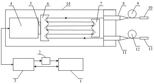
[0027] Such as figure 1 Shown, among the present invention:

[0028] Voice coil motor is a cylindrical voice coil motor working in linear reciprocating motion, its maximum stroke exceeds 10 mm, and its peak acceleration is greater than 316 m / s 2 , The motor has a built-in high-precision grating position encoder, which can realize position information reading with an accuracy of less than or equal to 0.15 microns.

[0029] The connector is a mechanical connection element that enables the positioning and connection of the voice coil motor and the mobile reflex module.

[0030] The voice coil motor in the present invention is connected with the computer through the driver, and the servo control of the motor movement is realized through the upper computer software in the computer. The voice coil motor and the driver are connected through a shielded cable to realize power supply and data interaction for the motor. The driver and the computer are connected through a shielded cab...


PUM

PropertyMeasurementUnit
Surface finishaaaaaaaaaa

Abstract

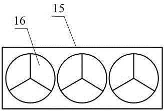
The invention discloses a large-stroke high-scanning frequency optical fiber delay line. The large-stroke high-scanning frequency optical fiber delay line comprises a mobile reflecting module and a fixed reflecting module which are mutually and oppositely arranged; the mobile reflecting module is connected with a drive motor through a connecting piece; the drive motor is connected to a computer through a driver, and motion control is performed by using upper computer software; each of the mobile reflecting module and the fixed reflecting module comprises a plurality of uniformly-arranged hollow aluminum pyramid reflecting mirrors, and the quantity of the hollow aluminum pyramid reflecting mirrors on the fixed reflecting module is one more than that of the hollow aluminum pyramid reflecting mirrors on the mobile reflecting module. According to the large-stroke high-scanning frequency optical fiber delay line disclosed by the invention, by utilizing the reverse reflection characteristic of the pyramid reflecting mirrors, reflected light can be strictly parallel to incident light, so that the effect of shaking on optical fiber coupling in the scanning process is reduced, and the system insertion loss is reduced; as the N pyramid reflecting mirrors and the N-1 pyramid reflecting mirrors are oppositely arranged, multiple reflections are formed in the two reflecting modules to realize optical path delay; in comparison with single pyramid reflecting mirrors, the delay scope can be improved by N times under the situation that the motor stroke is unchanged.

Description

technical field [0001] The invention belongs to the technical field of terahertz time-domain spectroscopy, and in particular relates to a large-stroke high-scanning-frequency optical fiber delay line. The present invention is applicable to the occasions of rapid collection of time-domain waveforms in most all-fiber terahertz time-domain spectroscopy systems. Background technique [0002] Terahertz time-domain spectroscopy (THz-TDS) technology can simultaneously detect the amplitude and phase information of THz pulses, and has shown great promise in many fields such as biology, material science, medical diagnosis, security inspection, non-destructive testing, military affairs, and physics and chemistry. It has rapidly developed into an interesting emerging research direction. In THz-TDS technology, the time-domain THz pulse waveform is realized by scanning and detecting the different delay parts of multiple THz pulses with femtosecond probe light, and the final THz pulse wav...

Claims


Application Information

Patent Timeline
IPC IPC(8): G02B6/28G02B26/10
CPCG02B26/10G02B6/2861
Inventor 刘乔黄华川朱礼国李江蒙建华翟朝辉钟森城周平伟杜良辉王德田邹逸彭其先李泽仁赵剑衡
Owner INST OF FLUID PHYSICS CHINA ACAD OF ENG PHYSICS
Learn More