
Automatic attenuation control circuit employing PWM chopping constant-current control

An automatic attenuation control and attenuation control technology, which is applied in the control system, motor generator control, electrical components, etc., can solve the problems of current fluctuation, insufficient attenuation rate, and constant attenuation rate, so as to reduce current fluctuation and optimize stability The effect of running and increasing the speed

Active Publication Date: 2016-08-24
杭州中科微电子有限公司
View PDF4 Cites 9 Cited by
  • Summary
  • Abstract
  • Description
  • Claims
  • Application Information

AI Technical Summary

Problems solved by technology

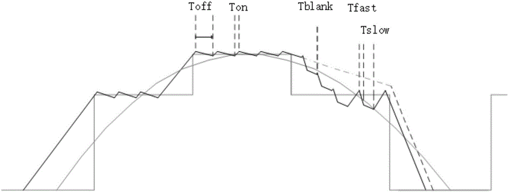
However, adding fast decay time will cause large current fluctuations on the steps. The greater the proportion of decay time, the greater the fluctuation, and the motor will run unstable and noisy.
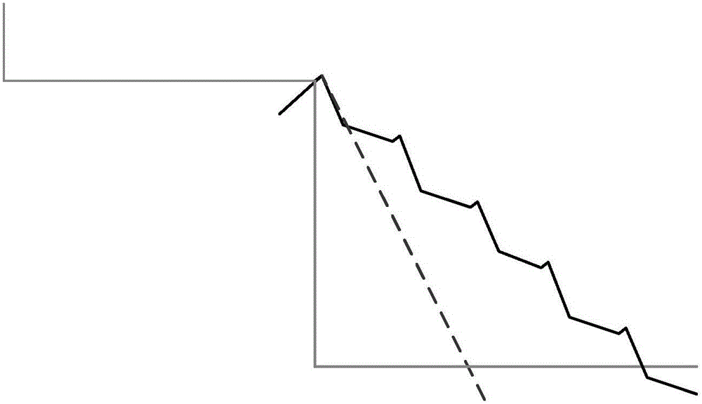
[0007] In addition, different currents have different height differences between adjacent steps. Under a small step height difference, the current will jump directly to the third step due to the large fast decay time (such as figure 2 As shown), it will cause distortion problems, how to optimize this situation; when there is a large step height difference (such as image 3 As shown), there is a problem of sinusoidal approximation distortion caused by too long decay time
[0008] Even within the same step, when the motor drive voltage increases, or when a motor with a small inductance is used, the charging rate increases, but the decay rate remains the same, or the fixed decay time is reduced, the drive circuit will appear as follows Figure 4 The waveform of the problem, within the Ton(min) time, the motor current rushes up, but within the fixed decay time, due to the insufficient decay rate, the current fails to decay below the current step value, so that the PWM chopping function cannot work normally

Method used


Image

  • Automatic attenuation control circuit employing PWM chopping constant-current control
  • Automatic attenuation control circuit employing PWM chopping constant-current control
  • Automatic attenuation control circuit employing PWM chopping constant-current control

Examples


Embodiment Construction

[0025] Such as Figure 6 As shown, the automatic decay control module auto decay is firstly designed. Under the action of STEP and comparator output COMP_O, the module generates four control signals through internal logic control; design the module circuit Toff&Tfast to generate Toff and Tfast of the required size time and Tblank time. Through the internal algorithm of autodecay, the required working mode is converted into the corresponding control signal slow, Tb, 2Tb, 25% Toff, the control signal selects and outputs different Tfast in the circuit Toff&Tfast, and is controlled by the internal logic synthesis output to the gate drive module GATE_D, GATE_D generates four control bits to control the DMOS tube of the H bridge, and the current is turned on and off. The current Im flows through the DMOS, and the motor current is detected by connecting the current-sense resistor Rs in series between the DMOS source of the lower tube and the ground, and the voltage Vsense=Im*Rs; the...


PUM


Abstract

The invention discloses an automatic attenuation control circuit employing PWM chopping constant-current control. The automatic attenuation control circuit comprises a logic control circuit, a comparator, a gate drive module, a current detection circuit, an H bridge output stage and an inductive load, wherein the logic control circuit comprises a core logic module, a self-attenuation control module and a time signal module; the core logic module is connected with the self-attenuation control module; the time signal module is connected with the self-attenuation control module; the self-attenuation control module is configured to convert a step signal and an output signal of the comparator into a control signal through an internal algorithm; and the control signal is output to the gate drive module through the time signal module. Automatic control on a current attenuation mode in a chopping constant-current working mode of a stepper motor is achieved; current fluctuation of the motor is reduced; stable operation of the motor is optimized; noise of the motor is reduced; meanwhile, the rotating speed of the motor is improved; and the automatic attenuation control circuit is suitable for being applied to a high-speed and high-precision motor drive circuit.

Description

technical field [0001] The invention relates to the field of motor drive, in particular to an automatic attenuation control circuit for PWM chopper constant current control applied to a stepping motor drive chip. Background technique [0002] Today, when electricity is the main energy source, the application of motors is ubiquitous. In motor drive applications, stepper motors have been increasingly widely used because they can precisely control the rotational displacement and rotational speed of the motor. With the higher demand of users for functions and performance, it is necessary to further improve the stability, efficiency, load capacity, high speed and other performance of the motor, and various control methods to improve the working condition of the motor are emerging. [0003] The technology of driving and controlling stepper motors has developed from the initial DC motor drive to H-bridge synchronous rectification drive, and then upgraded from full step control to s...

Claims


Application Information

Patent Timeline
Patent Type & Authority Applications(China)
IPC IPC(8): H02P8/12
CPCH02P8/12
Inventor 陈路鹏王良坤
Owner 杭州中科微电子有限公司
Learn More