Steel pipe circular weld mechanism

A technology of annular welding seam and steel pipe, applied in the field of annular welding seam mechanism of steel pipe, can solve the problems of high work intensity, troublesome operation, low welding efficiency, etc., and achieve the effects of reducing labor intensity, simple structure, and improving efficiency and quality.

Active Publication Date: 2016-08-31
GUANGDONG WALSALL STEEL PIPE IND
View PDF9 Cites 16 Cited by
  • Summary
  • Abstract
  • Description
  • Claims
  • Application Information

AI Technical Summary

Problems solved by technology

[0002] Welding is a manufacturing process and technology for joining metal or other thermoplastic materials by means of heating, high temperature or high pressure. According to the specific welding process, welding can be subdivided into gas welding, resistance welding, arc welding, induction welding and laser welding, etc. Special welding, steel pipes are widely used in our production and life. Steel pipes can be used in pipelines, thermal equipment, machinery industry, petroleum geological drilling, containers, chemical industry and special purposes. During the use of cylinder pipes, both ends of steel pipes need to be The flanges are welded separately, so that multiple steel pipes can be connected by flanges to meet the needs of use. In the welding process of traditional steel pipes, the flanges and steel pipes are gene

Method used


Image

  • Steel pipe circular weld mechanism

Examples


Embodiment Construction

[0009] In order to further describe the present invention, a specific implementation of a steel pipe girth weld mechanism will be further described below in conjunction with the accompanying drawings. The following examples are explanations of the present invention and the present invention is not limited to the following examples.

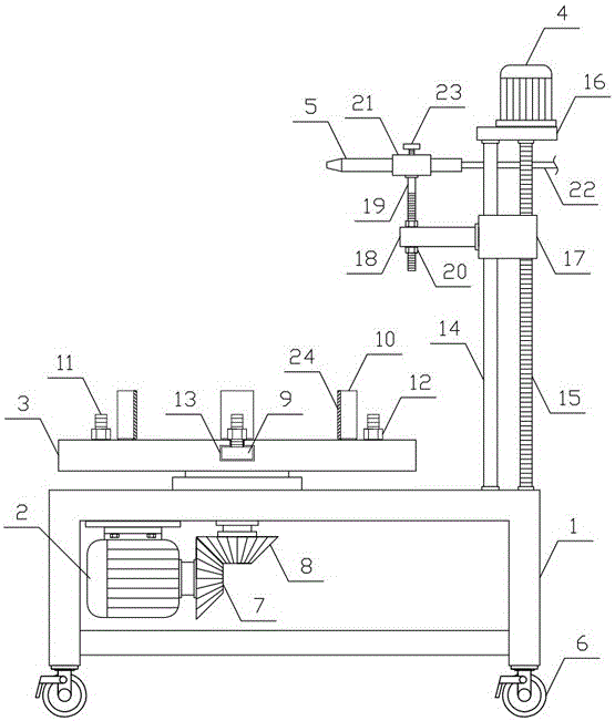
[0010] Such as figure 1 As shown, a steel pipe annular weld mechanism of the present invention includes a translation support 1, a rotating motor 2, a steel pipe placement plate 3, a lifting motor 4 and a steel pipe welding torch 5, and a plurality of universal wheels with brakes are uniformly arranged on the lower side of the translation support 1 6. The upper side of the translation support 1 is horizontally connected with a circular steel pipe placement plate 3, the rotation motor 2 is horizontally arranged on the lower side of the translation support 1, the output end of the rotation motor 2 is vertically provided with a main bevel gear 7, and ...


PUM


Abstract

The invention discloses a steel pipe circular weld mechanism and belongs to the field of steel pipe machining mechanical equipment. The steel pipe circular weld mechanism comprises a horizontal moving support, a rotation motor, a steel pipe holding plate, a lifting motor and a steel pipe welding gun, wherein a plurality of universal wheels with brakes are evenly arranged on the lower side of the horizontal moving support; the round steel pipe holding plate is horizontally and rotatably connected on the upper side of the horizontal moving support; a plurality of steel pipe clamping mechanisms are symmetrically arranged on the steel pipe holding plate in the radial direction; a lifting guide rod and a lifting screw rod are vertically arranged on one side of the upper portion of the horizontal moving support correspondingly; a lifting support can go up and down along the lifting guide rod; hold-down nuts are connected on an adjustment screw rod on the upper side and the lower side of a fixation plate in a threaded mode; a horizontal moving sleeve is horizontally arranged at the upper end of the adjustment screw rod; and the steel pipe welding gun can move horizontally along the horizontal moving sleeve. The steel pipe circular weld mechanism is reasonable in structural design and capable of vertically and firmly fixing steel pipes and conducting circular welding on the steel pipes conveniently and efficiently, and meets the requirements for machining and using.

Description

technical field [0001] The invention belongs to the field of steel pipe processing machinery and equipment, and in particular relates to a steel pipe annular weld mechanism. Background technique [0002] Welding is a manufacturing process and technology for joining metal or other thermoplastic materials by means of heating, high temperature or high pressure. According to the specific welding process, welding can be subdivided into gas welding, resistance welding, arc welding, induction welding and laser welding, etc. Special welding, steel pipes are widely used in our production and life. Steel pipes can be used in pipelines, thermal equipment, machinery industry, petroleum geological drilling, containers, chemical industry and special purposes. During the use of cylinder pipes, both ends of steel pipes need to be The flanges are welded separately, so that multiple steel pipes can be connected by flanges to meet the needs of use. In the welding process of traditional steel p...

Claims


Application Information

Patent Timeline
IPC IPC(8): B23K37/047B23K37/053B23K7/10B23K101/06
CPCB23K7/10B23K37/047B23K37/0533B23K2101/04
Inventor 曹建栋
Owner GUANGDONG WALSALL STEEL PIPE IND
Why Eureka
Try Eureka