Energy self-sufficiency high concentrated sewage treating system and method

A technology of sewage treatment system and sewage treatment method, which is applied in the direction of energy wastewater treatment, biological water/sewage treatment, multi-stage water/sewage treatment, etc., and can solve problems such as unfavorable sewage treatment efficiency, reduced sewage treatment cost, and increased production cost. , to avoid excessive acidity, improve overall treatment efficiency, and reduce energy consumption

Active Publication Date: 2016-08-31
WUHAN HUIZHONG DACHUAN AUTOMATIC CONTROL EQUIP CO LTD
View PDF4 Cites 1 Cited by
  • Summary
  • Abstract
  • Description
  • Claims
  • Application Information

AI Technical Summary

Problems solved by technology

[0003] However, the above-mentioned anaerobic sludge reactor still has the following disadvantages: on the one hand, the sewage needs to be treated by hydrolysis and acidification before entering the anaerobic sludge reactor, and the hydrolysis and acidification treatment will easily lead to high acidity of the sewage, thereby inhibiting the efficiency of the anaerobic sludge reactor. The growth of methane bacteria is not conducive to the improvement of the sewage treatment efficiency in the anaerobic sludge reactor, which in turn leads to a decrease in the overall treatment efficiency. Although it can be solved by adjusting the pH value during the hydrolytic acidification process to reduce the acidity, it will easily lead to production costs. The increase is not conducive to the reduction of sewage treatment costs; on the other hand, the anaerobic sludge reactor sewage treatment consumes a lot of energy, which is not conducive to energy saving

Method used


Image

  • Energy self-sufficiency high concentrated sewage treating system and method

Examples


Embodiment Construction

[0027] In order to make the object, technical solution and advantages of the present invention clearer, the present invention will be further described in detail below in conjunction with the accompanying drawings and embodiments. It should be understood that the specific embodiments described here are only used to explain the present invention, not to limit the present invention.

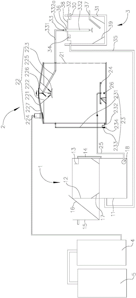
[0028] see figure 1 , The embodiment of the present invention provides a self-sufficient high-concentration sewage treatment system, including hydrolytic acidification equipment, 1, anaerobic reactor 2, sludge treatment equipment 3, desulfurization tower 4 and biogas power generation equipment 5. in,

[0029] The hydrolytic acidification device 1 comprises a hydrolytic acidification tank 11, a first settling tank 12 covering the opening of the upper end of the hydrolytic acidification tank 11, a first overflow weir 13 arranged in the first settling tank 12, and a first overflow weir 13 connected t...


PUM


Abstract

The invention discloses an energy self-sufficiency high concentrated sewage treating system and method. The system comprises a hydrolytic acidification device, an anaerobic reactor, a sludge treating device, a desulfurizing tower and a marsh gas power generation device. The sludge treating device comprises a second sedimentation basin, a second overflow weir, a water inlet pipe and an oxygen dissolving instrument. The second overflow weir is communicated with the hydrolytic acidification pool through a backflow pipe, and the water inlet is provided with a jet flow hole and an adjusting valve. The method comprises the steps of hydrolytic acidification, anaerobic fermentation, sludge treatment and desulfuration power generation in sequence. Due to the fact that the sludge treating device is provided with the jet flow hole to adjust the oxygen dissolving content of the reaction liquid surface, it is ensured that reaction produces nitrite, the formed nitrite backflows to the hydrolytic acidification pool, acidity of acidized sewage is prevented from being too high, and overall sewage treating efficiency is improved; meanwhile, the marsh gas power generation device is adopted, so that marsh gas produced in the anaerobic reaction stage is used for power generation, the requirements of sewage treatment for energy consumption are met, and energy consumption can be lowered.

Description

technical field [0001] The invention relates to the technical field of sewage treatment, in particular to an energy self-sufficient high-concentration sewage treatment system and method. Background technique [0002] Conventional anaerobic sludge reactors include UASB, EGSB, IC, etc. The principle of wastewater treatment is basically that the sewage to be treated is introduced into the reactor as evenly as possible, and the sewage entering the reactor is mixed with granular or flocculent sludge The contact reaction occurs, and part of the biogas (mainly methane and carbon dioxide) produced by the reaction adheres to the sludge, moves upward with the biogas, and hits the three-phase separator to realize the three-phase separation of solid, liquid and gas. Anaerobic sludge reactors are also widely used in sewage treatment in different fields because of their different pertinence. [0003] However, the above-mentioned anaerobic sludge reactor still has the following disadvanta...

Claims


Application Information

Patent Timeline
Patent Type & Authority Applications(China)
IPC IPC(8): C02F3/28
CPCC02F3/286C02F3/2866C02F2203/002C02F2301/08C02F2209/005C02F3/2873C02F11/04C02F2209/22C02F2209/42C02F2303/10Y02W10/30Y02E50/30C02F1/004C02F9/00C02F11/06C02F2001/007
Inventor 刘川刘晓川
Owner WUHAN HUIZHONG DACHUAN AUTOMATIC CONTROL EQUIP CO LTD
Why Eureka
Try Eureka