
Rotary magnetron target and horizontal magnetron sputtering coating equipment

A magnetron target, rotary technology, used in sputtering coating, ion implantation coating, vacuum evaporation coating and other directions, can solve the problem of prolonging the coating cycle of the vacuum coating system, difficult to improve the coating efficiency, and affecting the vacuuming time of the equipment and other problems, to achieve the effect of shortening the coating cycle of the workpiece, shortening the production cycle and shortening the cycle cycle

Active Publication Date: 2016-08-31
ZHAOQING KERUN VACUUM EQUIP
View PDF5 Cites 3 Cited by
  • Summary
  • Abstract
  • Description
  • Claims
  • Application Information

AI Technical Summary

Problems solved by technology

However, in actual production, the vacuuming effect of the vacuum coating system with this structure is not ideal, especially for the vacuuming of the rough pumping chamber. Because the front-stage pumping capacity of the Roots pump is often poor, it is difficult to achieve low pressure in the rough pumping chamber. The strong state makes it difficult for the workpiece to get better buffer treatment in the rough pumping chamber, which often easily affects the processing effect of the subsequent processing steps; at the same time, when the rough pumping chamber is vacuumed, it takes a long time, so it also prolongs the entire vacuum coating process. The coating cycle of the system, the coating efficiency is difficult to improve
[0004] In addition, after the coating equipment has been working for a period of time, there will be residual film in the coating chamber, and it will become thicker and thicker. Even if it is cleaned, a part of it will remain on the wall of the coating chamber, because the outgassing amount of these residual films will be relatively large , in the process of pumping the coating chamber, the gas remaining in the film layer will be released slowly, which will not only affect the vacuuming time of the equipment, but also affect the coating effect of the new workpiece

Method used


Image

  • Rotary magnetron target and horizontal magnetron sputtering coating equipment
  • Rotary magnetron target and horizontal magnetron sputtering coating equipment
  • Rotary magnetron target and horizontal magnetron sputtering coating equipment

Examples


Embodiment 1

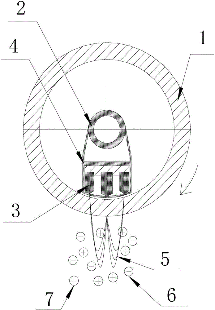
[0035] A kind of rotary magnetron target of present embodiment, such as figure 1 As shown, it includes a target 1, a magnetic core 2 and a magnet 3. The magnetic core is arranged in the middle of the target, and at least one magnet is arranged on the outer periphery of the magnetic core. The end of the magnet facing the target is tapered.

[0036] The target is a hollow cylindrical structure, and the magnetic core and magnet are located in the space in the middle of the target.

[0037] The magnetic core is a hollow cylindrical structure, the outer periphery of the magnetic core is provided with a fixing frame 4, and the magnet is installed on the fixing frame. The fixing frame can adopt a fan-shaped structure or a support frame similar to a fan-shaped structure. Its main function is to install the magnet. The fixing frame part located at the outer circumference of the tapered end of the magnet can be an open structure (that is, the tapered end of the magnet is directly close ...

Embodiment 2

[0043] This embodiment is a rotary magnetron target. Compared with Embodiment 1, the difference is that: in the same axial section of the target (that is, in the vertical direction of the workpiece conveying direction), when the magnet is a split structure , the magnet is composed of multiple sub-blocks distributed side by side, each sub-block is a cylindrical structure, and the tapered end of each sub-block is conical.

[0044] The target and the magnetic core are concentrically arranged, and the magnet is located in the annular space formed between the target and the magnetic core; in the same radial section of the target (that is, in the direction parallel to the workpiece conveying direction), there are three sets of magnets on the outer periphery of the magnetic core , three groups of magnets are installed side by side on the fixed frame, that is, in this structure, there are three groups of magnets composed of blocks in the entire rotating target. However, in practical a...

Embodiment 3

[0046] This embodiment is a rotary magnetron target. Compared with Embodiment 1, the difference is that: in the same axial section of the target (that is, in the vertical direction of the workpiece conveying direction), when the magnet is a split structure , the magnet is composed of a plurality of sub-blocks distributed side by side, each sub-block is a cuboid structure, and the tapered end of each sub-block is in the shape of a quadrangular pyramid.

[0047] The target and the magnetic core are concentrically arranged, and the magnet is located in the annular space formed between the target and the magnetic core; in the same radial section of the target (that is, in the direction parallel to the workpiece conveying direction), there are three sets of magnets on the outer periphery of the magnetic core , three groups of magnets are installed side by side on the fixed frame, that is, in this structure, there are three groups of magnets composed of blocks in the entire rotating ...


PUM


Abstract

The invention discloses a rotary magnetron target and horizontal magnetron sputtering coating equipment. The rotary magnetron target comprises a target, a magnetic core and a magnet, wherein the magnetic core is arranged at the middle part of the target, at least one magnet is arranged at the periphery of the magnetic core, and one end facing the target, of the magnet, is conical. The horizontal magnetron sputtering coating equipment comprises a front pre-pumping chamber, a front rough-pumping chamber, a front fine-pumping chamber, a front buffering chamber, a coating chamber, a rear buffering chamber, a rear fine-pumping chamber, a rear rough-pumping chamber and a rear pre-pumping chamber which are sequentially connected, wherein one or more coating chambers are provided, and one rotary magnetron target is arranged in each coating chamber, and located above a workpiece. According to the rotary magnetron target, the tail end of the magnet is designed to be a tip, thus the distribution density of magnetic force lines on the surface of the target is enhanced, and the number of the sputtered target particles can be increased, and then the coating efficiency of the surface of the workpiece is increased. The rotary magnetron target is applied to the horizontal magnetron sputtering coating equipment, thus the coating efficiency of the workpiece can be effectively increased, and the production cycle of a whole process line is shortened, and then the production efficiency is increased.

Description

technical field [0001] The invention relates to the technical field of magnetron sputtering coating, in particular to a rotary magnetron target and a horizontal magnetron sputtering coating device with the rotary magnetron target. Background technique [0002] In the magnetron sputtering coating system, a planar magnetron target or a rotating magnetron target is generally used in the coating chamber to sputter and coat the surface of the workpiece. Among them, the rotary magnetron target coating is to rely on electrons to hit argon molecules to turn them into argon ions, and then under the action of magnetic and electric fields, argon ions bombard the surface of the target at high speed, and the required materials are converted into ions and molecules. Splash out, plated on the surface of the workpiece. At present, in the general-purpose rotary magnetron target, the end of the magnet is generally a planar structure. In actual production, the distribution of the magnetic fie...

Claims


Application Information

Patent Timeline
Patent Type & Authority Applications(China)
IPC IPC(8): C23C14/35
CPCC23C14/3407C23C14/35
Inventor 朱建明李金清张闰华
Owner ZHAOQING KERUN VACUUM EQUIP
Learn More