Novel electric thermal storage system

A new type of electric heat storage technology, applied in the field of heat storage system, can solve the problems that the heat storage system cannot meet the user's free switching, the solid-liquid phase change material is expensive, and the iron oxide-based solid strength is poor, so as to save the laying cost, The effect of compact structure and stable performance

Inactive Publication Date: 2016-08-31
成都市鑫裕华科技有限公司
View PDF0 Cites 1 Cited by
  • Summary
  • Abstract
  • Description
  • Claims
  • Application Information

AI Technical Summary

Problems solved by technology

At present, domestic energy storage electric boilers mainly include atmospheric water tank split energy storage electric boilers, pressurized water tank energy storage electric boilers, electric heaters with iron oxide-based solids as heat storage materials, and solid-liquid phase change materials. It is an energy storage device for energy storage materials, but because of the small heat capacity of atmospheric

Method used


Image

  • Novel electric thermal storage system

Examples


Example Embodiment

[0026] Example 1:

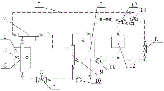
[0027] The main structure of this embodiment, such as figure 1 As shown, it includes a heat storage 1, a heater 2, an inner circulation system, and an outer circulation system; the inner circulation pipe represented by the solid arrow in the inner circulation system is sequentially connected to the heat extractor 3, the heat exchanger 4, and the secondary The circulation system and the controller 6 are closed; the secondary circulation system is formed by connecting the inner circulation pipeline to the liquid storage tank 5, the inner circulation water pump 10 and the B heat exchanger 9 in turn; the outer circulation system is represented by the dotted arrow The outer circulation pipeline is connected in turn with the A heat exchanger 4, the user system, the outer circulation water pump 11 and the B heat exchanger 9; it is characterized in that: the user system includes a radiator 8 and a faucet 13; the faucet 13 is Single-handle double-valve combined faucet...

Example Embodiment

[0030] Example 2:

[0031] This embodiment is further optimized on the basis of the above embodiment, and further, as figure 1 As shown, a water softening device 12 is installed on the side of the faucet 13 that is connected to the valve of the water supply pipe. The water softening device 12 can soften the water that enters the external circulation system from the water supply pipe and reaches the water intake through the external circulation system. It is used by the user, and when heating, since there is no need to continuously connect to the water source, the water softening device 12 will stop operating because there is no water flow through. The other parts of this embodiment are the same as the above-mentioned embodiment, so they will not be described again.

[0032] It can be understood that the electrical heat storage system structure according to an embodiment of the present invention, for example, the working principles and working processes of the radiator 8 and the B ...


PUM


Abstract

The invention discloses a novel electric thermal storage system which comprises a thermal storage device, heaters, an inner circulating system and an outer circulating system, wherein the outer circulating system is composed of a user system; the user system is composed of a radiator and a water faucet; the water faucet is a single-handle and double-valve combination type water faucet; the sizes and the movement conditions of two valves are completely consistent; a valve inlet of the water faucet is connected to an external pipeline; a valve outlet of the water faucet is a water fetching hole; the other valve inlet of the water faucet is connected to a water supply pipeline; and the other valve outlet of the water faucet is connected between the radiator and an outer circulating water pump. According to the novel electric thermal storage system, the system structure is optimized by adopting the unique design of the user system, the infrared radiation type heaters, a full-automatic controlled intelligent controller and the like and with high-density iron-based alloy as a thermal storage material, a user can freely switch functions of warming and removing hot water, and the novel electric thermal storage system is small in occupying area, high in thermal efficiency, convenient in operation, stable in performance, high in safety and low in running cost and is suitable for wide popularization.

Description

technical field [0001] The invention relates to the field of heat storage systems, in particular to a novel electric heat storage system. Background technique [0002] The use of clean energy for heating and hot water supply is an important aspect of improving the urban atmospheric environment and reducing pollution. At present, coal-fired boilers are generally used as heating boilers in cities in our country, which cause extremely serious air pollution. However, although the use of fuel oil, gas or general electric heating boilers can reduce the degree of air pollution, the operating cost of heating alone is relatively high, so it is not suitable for popularization and use. In recent years, my country's daytime electricity consumption has increased year by year, increasing the peak-to-valley electricity difference. In order to reduce the peak-to-valley power difference, the power management department has formulated a preferential policy for using valley power to reduce t...

Claims


Application Information

Patent Timeline
IPC IPC(8): F24D3/08F24D19/10
CPCF24D3/087F24D19/1066
Inventor 付建军
Owner 成都市鑫裕华科技有限公司
Why Eureka
Try Eureka