Photovoltaic ultraviolet test box

A test chamber and ultraviolet technology, applied in the monitoring of photovoltaic power generation, photovoltaic modules, photovoltaic systems, etc., can solve the problems of test result error, aging inconsistency, lamp failure, etc., to ensure safety, achieve stability, and reduce distance. Effect

Inactive Publication Date: 2016-08-31
SHANGHAI LINPIN INSTR
View PDF9 Cites 1 Cited by
  • Summary
  • Abstract
  • Description
  • Claims
  • Application Information

AI Technical Summary

Problems solved by technology

[0003] (1) No special circulating air duct is designed, so the temperature uniformity of the aging box is not very good, and the aging is inconsistent;
[0004] (2) Since only one type of ultraviolet lamp is equipped, due to the characteristics of the wavelength of the lamp, it cannot simulate the ultraviolet aging of nature to the greatest extent;
[0005] (3) Even if two kinds of lamp tubes are equipped, they cannot be installed in the test chamber at one time. After the test of one kind of lamp tube is completed, another lamp tube should be replaced;
[0006] (4) It is not equipped with an ultraviolet light probe. Most of them use a hand-held irradiance meter to detect the light intensity before starting up. After the machine is working, it cannot monitor the light intensity in real time. The lamp will fail during use, resulting in error in test results;
[0007] (5) Ordinary ballasts are used, and the light intensity cannot be adjusted;
[0008] (6) Not equipped with a touch screen controller, the degree of automation is not high, and the data recording function is not strong

Method used


Image

  • Photovoltaic ultraviolet test box
  • Photovoltaic ultraviolet test box
  • Photovoltaic ultraviolet test box

Examples


Embodiment Construction

[0031] Below in conjunction with accompanying drawing, the present invention will be further described as follows:

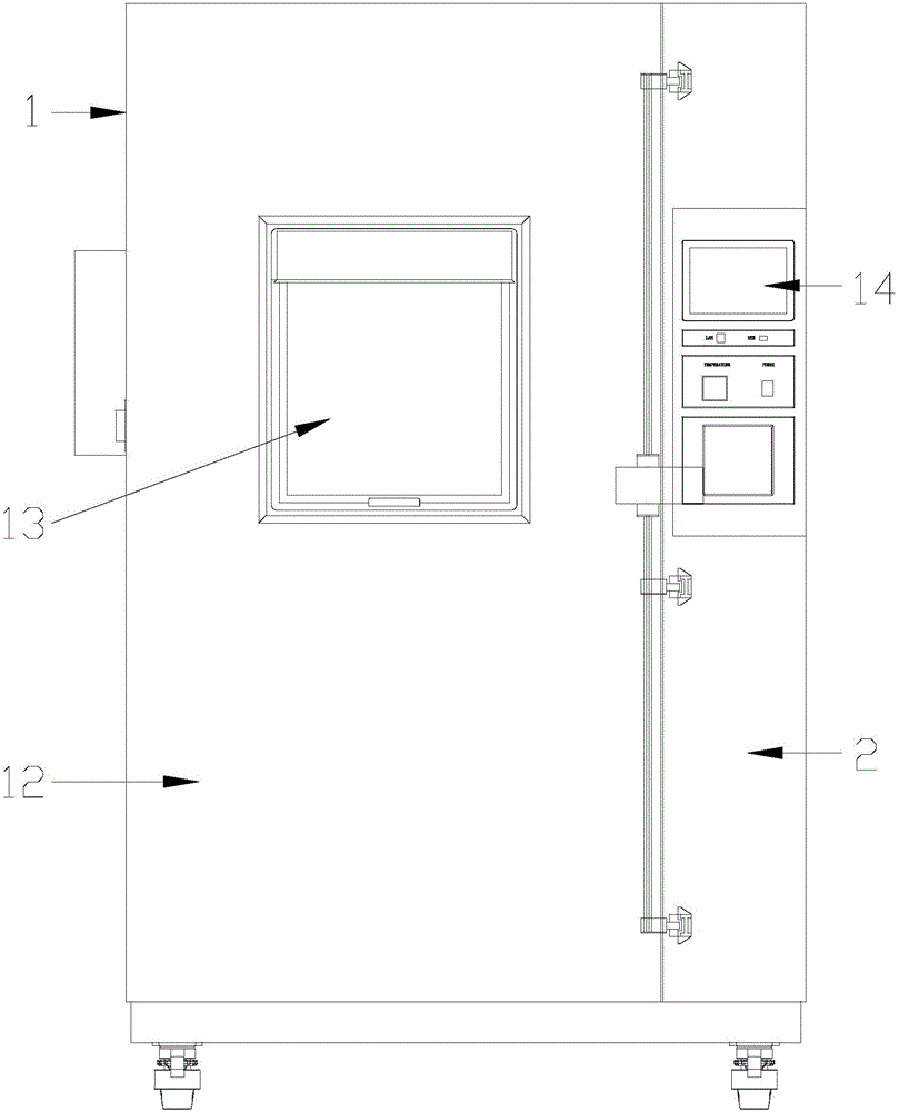
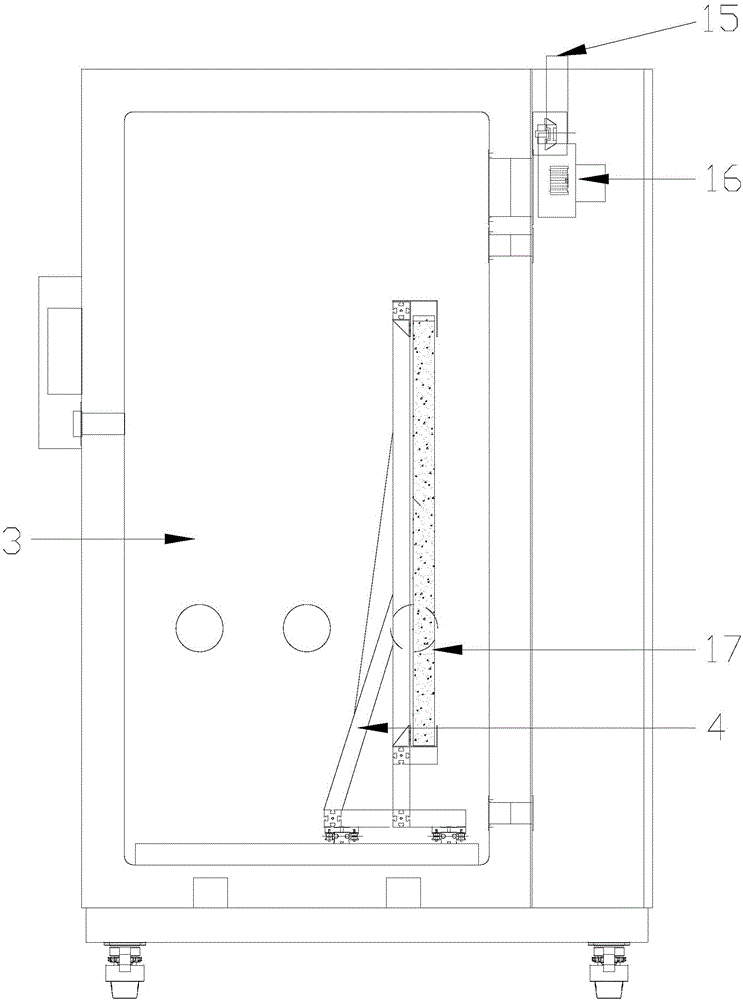
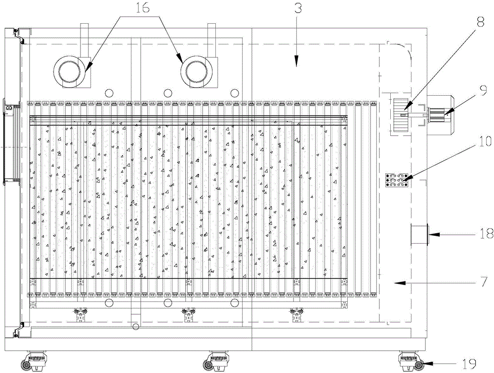
[0032] As shown in the drawings, the present invention includes: a box body 1, an electrical cabinet 2 is connected to one side of the box body 1, an electrical system is arranged inside the electrical cabinet 2, a working room 3 is arranged in the box body 1, and a working room 3 is arranged in the working room 3 The sample track frame 4 and the ultraviolet lamp tube, the ultraviolet lamp tube is installed on the side wall connected to the cabinet 1 and the electrical cabinet 2, the ultraviolet lamp tube includes UVA lamp tube 5 and UVB lamp tube 6, UVA lamp tube 5, UVB lamp tube 6 are respectively equipped with multiple branches, UVA lamp tube 5 and UVB lamp tube 6 are arranged at intervals, UVA lamp tube 5 and UVB lamp tube 6 are respectively connected to the electrical system by lines, and the illumination direction of UVA lamp tube 5 and UVB lamp tube 6 is d...


PUM

PropertyMeasurementUnit
wavelengthaaaaaaaaaa

Abstract

The invention relates to a photovoltaic ultraviolet test box including a box body. An electrical cabinet is connected to one side of the box body. An electrical system is arranged in the electrical cabinet. A work chamber is arranged in the box body. A sample rail bracket and ultraviolet lamp tubes are arranged in the work chamber. The ultraviolet lamp tubes are arranged on the side wall, which is connected to the electrical cabinet, of the box body. The ultraviolet lamp tubes include a plurality of UVA lamp tubes and a plurality of UVB lamp tubes, wherein the UVA lamp tubes and the UVB lamp tubes are arranged at intervals and are respectively connected to the electrical system through lines. Irradiation directions of the UVA lamp tubes and the UVB lamp tubes are arranged directly towards the sample rail bracket. An air circulating channel is arranged at the rear side of the work chamber in the box body and is communicated with the work chamber. The photovoltaic ultraviolet test box not only enables air in all corners in the text box to flow completely, thereby ensuring the temperature in the text box everywhere to be controlled within a designed temperature range as most as possible, but also is free of switching the lamp tubes manually during operation and is high in automation degree.

Description

[technical field] [0001] The invention relates to the technical field of environmental test instruments, in particular to a photovoltaic ultraviolet test box. [Background technique] [0002] With the depletion of traditional energy sources and the use of petroleum and coal, the environment is polluted greatly, and people's demand for new energy sources is becoming more and more urgent. The use of photovoltaic solar panels makes it possible to use solar energy on a large scale, but on the basis of existing technologies, how to produce reliable solar panels and enable them to work for a long time to generate economic benefits, for this reason, the National Standard Electrician Organization issued a IEC-61646 is a test method specifically for solar panels. Therefore, the photovoltaic UV test box came into being. Putting the sample in the test box for UV aging test can quickly discover the UV resistance of the sample, find problems and improve them in time, so as to minimize th...

Claims


Application Information

Patent Timeline
Patent Type & Authority Applications(China)
IPC IPC(8): G01N17/00H02S50/15
CPCG01N17/002G01N17/004H02S50/15Y02E10/50
Inventor 孙光林
Owner SHANGHAI LINPIN INSTR
Why Eureka
Try Eureka