Electrochemical water treatment device and method utilizing same to treat water
A kind of water treatment equipment, electrochemical technology, applied in electrochemical water treatment equipment, using this equipment in the field of water treatment, can solve the problems of great influence on treatment efficiency, poor electrochemical treatment effect, difficult to remove solid substances, etc., to avoid Effects of fouling deposition, reactor size reduction, and treatment cost reduction
- Summary
- Abstract
- Description
- Claims
- Application Information
AI Technical Summary
Problems solved by technology
Method used
Image
Examples
Embodiment 1
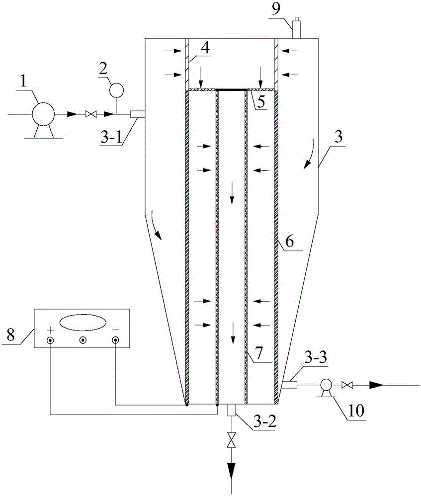
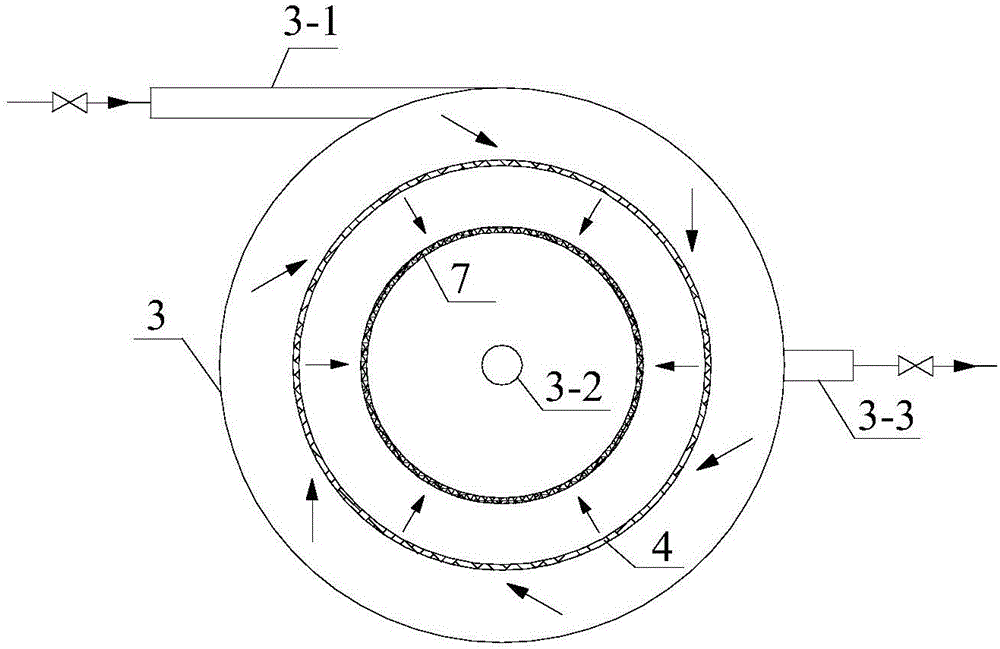
[0040] Electrochemical water treatment equipment, see Figures 1 to 2 , including water inlet pump 1, flow meter 2, reaction device 3, primary coarse filter 4, secondary fine filter 5, cathode 6, anode 7, power supply 8, exhaust valve 9, sewage pump 10 and hydrogen concentration alarm device 14.
[0041]The water inlet pump 1 is connected to the water inlet of the reaction layer; the upper part of the reaction device 3 is cylindrical, the lower part is an inverted truncated cone, the upper part is provided with a tangential water inlet 3-1, the lower end of the bottom is provided with a water outlet 3-2, and the bottom side wall There is a sewage outlet 3-3 connected to the sewage pump 10; the primary coarse filter 4 is a cylindrical stainless steel filter, which is located on the top of the center of the reaction device 3; the secondary fine filter 5 is a circular stainless steel filter , located at the bottom of the primary coarse filter 4; the anode 7 is a cylindrical tita...
Embodiment 2
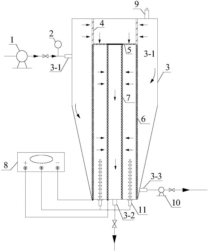
[0047] Electrochemical water treatment equipment, see image 3 , which is basically the same as that of Embodiment 1, except that it also includes an ultrasonic device 11, which is of the vibrating rod type, is arranged between the cathode 6 and the anode 7, and is connected to the power source 8.
Embodiment 3
[0049] Electrochemical water treatment equipment, see Figure 4 , is basically the same as Example 1, except that it also includes an air intake pump 13 and a porous aeration plate 12, and the air intake pump 13 passes gas into the reaction apparatus 3 through the porous aeration plate 12 located at the bottom of the reaction apparatus 3; Optionally, the gas introduced may be air, nitrogen, ozonated gas, etc.
PUM
 Abstract
Description
Claims
Application Information
 - R&D
- Intellectual Property
- Life Sciences
- Materials
- Tech Scout
- Unparalleled Data Quality
- Higher Quality Content
- 60% Fewer Hallucinations
Browse by: Latest US Patents, China's latest patents, Technical Efficacy Thesaurus, Application Domain, Technology Topic, Popular Technical Reports.
© 2025 PatSnap. All rights reserved.Legal|Privacy policy|Modern Slavery Act Transparency Statement|Sitemap|About US| Contact US: help@patsnap.com


