
Laminated solar cell and preparation method thereof

Inactive Publication Date: 2016-09-07
SUZHOU GCLSI SCI & TECH IND APPL RES INST CO LTD +2
View PDF4 Cites 18 Cited by
  • Summary
  • Abstract
  • Description
  • Claims
  • Application Information

AI Technical Summary

Problems solved by technology

[0005] Based on this, it is necessary to address the serious problem of short-circuit current loss in existing tandem solar cells, and to provide a tandem solar cell that reduces short-circuit current loss

Method used


Image

  • Laminated solar cell and preparation method thereof
  • Laminated solar cell and preparation method thereof
  • Laminated solar cell and preparation method thereof

Examples


Embodiment Construction

[0027] In order to make the object, technical solution and advantages of the present invention clearer, the present invention will be further described in detail below in conjunction with specific embodiments. It should be understood that the specific embodiments described here are only used to explain the present invention, and are not intended to limit the present invention.

[0028] It should be noted that when an element is referred to as being “disposed on” another element, it may be directly on the other element or there may also be an intervening element. When an element is referred to as being "connected to" another element, it can be directly connected to the other element or intervening elements may also be present. The terms "vertical," "horizontal," "left," "right," and similar expressions are used herein for purposes of illustration only and are not intended to represent the only embodiments.

[0029] Unless otherwise defined, all technical and scientific terms u...


PUM

PropertyMeasurementUnit
Heightaaaaaaaaaa

Abstract

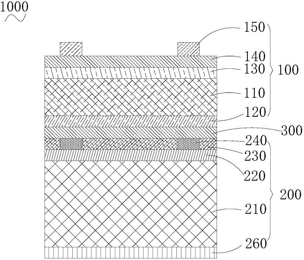
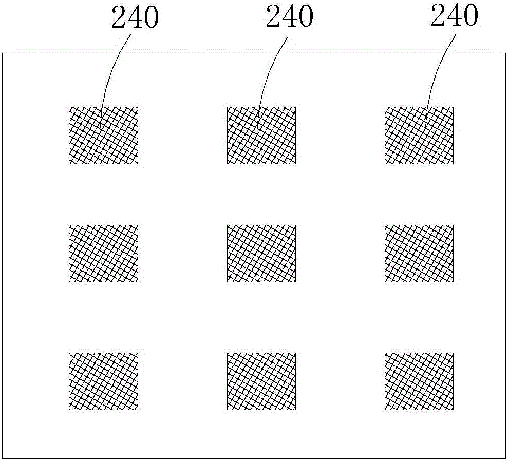
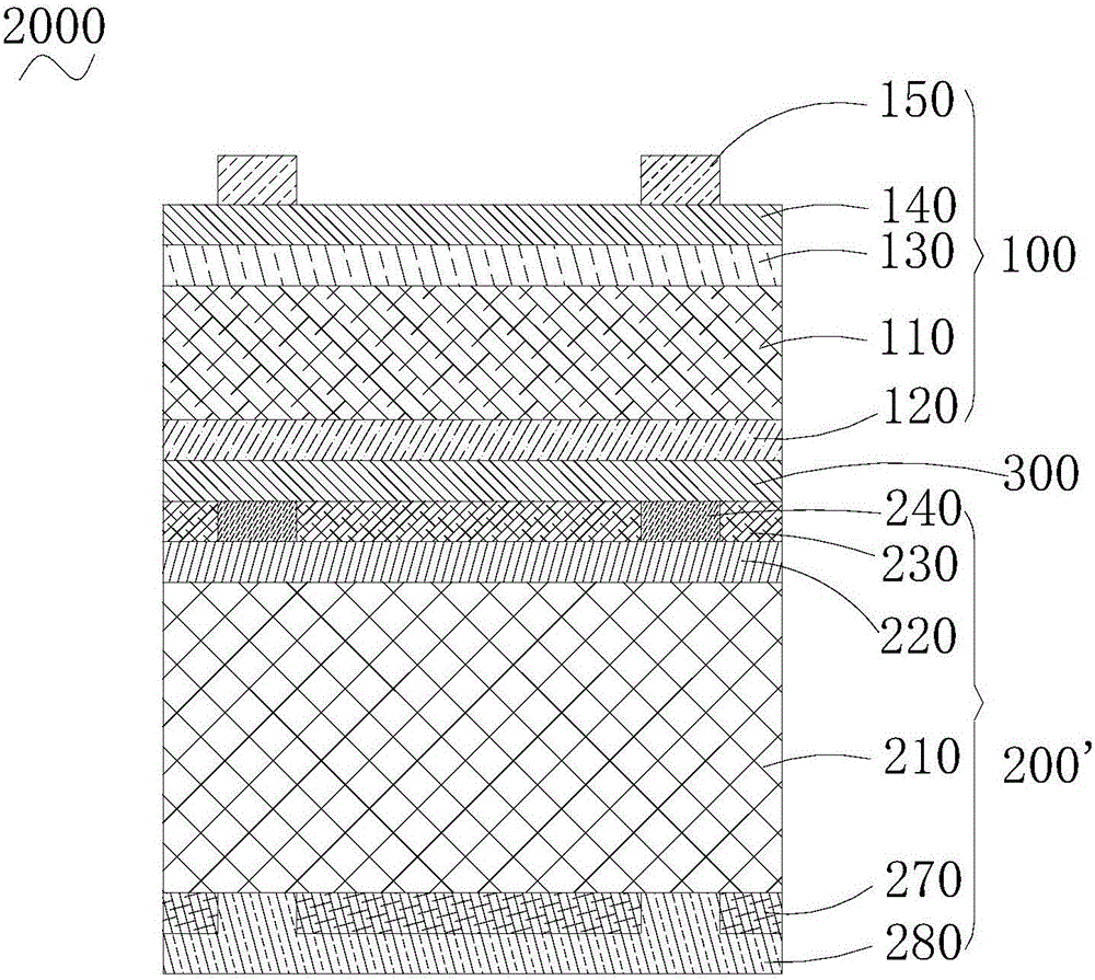
The invention relates to the field of a solar battery cell, and specifically discloses a laminated solar cell. The laminated solar cell comprises a top cell unit, a middle layer and a bottom unit layer which are arranged successively. The hole transport layer of the top cell unit is located on the backlight side of a photosensitive layer. The bottom cell unit is a P type silicon cell. According to the laminated solar cell, the P type silicon cell is matched with an inverted perovskite cell, the hole transport layer is located on the backlight side of the photosensitive layer, moreover, an electron transport layer is located at the light incident side of the photosensitive layer, therefore, strong absorption of the hole transport layer to light is avoided, the energy of sunlight entering the photosensitive layer is improved, and the loss of a short circuit current is reduced. Moreover, the PN of the P type silicon cell is relatively close to the light incident side, the absorption of the bottom cell to the light is improved, and the performance of the laminated solar cell is further improved. The integral cost of the laminated solar cell is reduced by use of the P type silicon cell. The invention also discloses a preparation method of the laminated solar cell.

Description

technical field [0001] The invention relates to the field of solar cells, in particular to a stacked solar cell and a preparation method thereof. Background technique [0002] The energy distribution of the solar spectrum is broad, and a semiconductor material can only absorb photons with energies higher than its energy gap value. The photons with lower energy in sunlight will pass through the battery and cannot be used; the excess energy of high-energy photons exceeding the energy gap width will be transferred to the lattice atoms of the battery material itself through the energy pyrolysis of photogenerated carriers to make the material itself fever. None of these energies can be transferred to the load through photogenerated carriers and become effective electrical energy. Therefore, the theoretical conversion efficiency of single-junction solar cells is generally low. [0003] As a result, stacked solar cells have emerged, which are generally composed of three parts: a...

Claims


Application Information

Patent Timeline
IPC IPC(8): H01L51/42H01L51/48
CPCH10K30/152H10K30/10Y02E10/549
Inventor 杨黎飞张闻斌王琪
Owner SUZHOU GCLSI SCI & TECH IND APPL RES INST CO LTD
Learn More