Photovoltaic energy storage system with charging control equipment and control method of photovoltaic energy storage system

A charging control and photovoltaic energy storage technology, applied in the field of photovoltaic energy storage system and its control, to achieve the effect of increasing storage capacity, simple structure, and improving charging efficiency

Inactive Publication Date: 2016-09-07
深圳智慧能源技术开发有限公司
View PDF3 Cites 2 Cited by
  • Summary
  • Abstract
  • Description
  • Claims
  • Application Information

AI Technical Summary

Problems solved by technology

According to the research, the system effect of battery internal resistance and state of charge, a pair of related variables, has not been fully valued. The industry hopes to find a technology that can increase the system's stored power, effectively prolong the service life of the battery pack, and reduce the system's power generation cost. Program

Method used


Image

  • Photovoltaic energy storage system with charging control equipment and control method of photovoltaic energy storage system
  • Photovoltaic energy storage system with charging control equipment and control method of photovoltaic energy storage system
  • Photovoltaic energy storage system with charging control equipment and control method of photovoltaic energy storage system

Examples


Embodiment 1

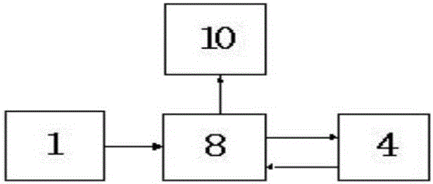
[0068] A low-power photovoltaic energy storage system is designed, which consists of a 200W photovoltaic module 1 , two 12V100Ah lead-acid maintenance-free battery packs 4 connected in series, and the charging control device 11 .

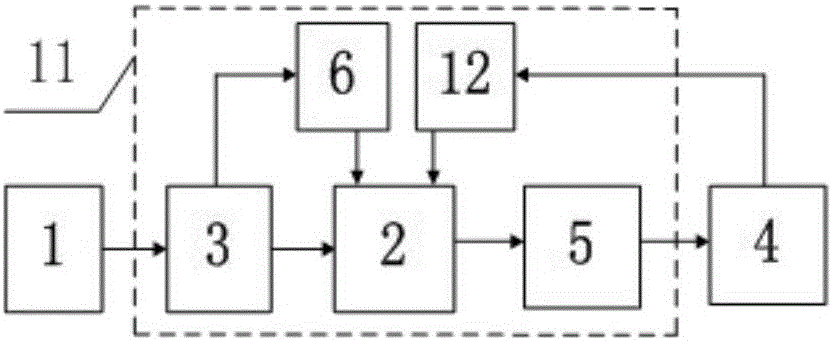
[0069] The charging control device 11 includes a measurement and control device 2, a photovoltaic input terminal 3, a power output interface 5, a photovoltaic acquisition device 6 and a patrol device 12, and the measurement and control device 2 is electrically connected to the power output terminal of the photovoltaic module 1 through the photovoltaic input terminal 3; The signal input terminals of the detection device 12 are respectively connected to the two ends of two storage batteries (battery modules), and the signal output terminals thereof are connected to the measurement and control device 2; The control logic switch connects the three external terminals of the two batteries in series, that is, respectively connects the two ends of the batter...

Embodiment 2

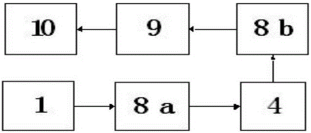
[0077] Change the two 12V100Ah lead-acid maintenance-free storage batteries described in Example 1 into four 6V100Ah lead-acid maintenance-free storage batteries, and connect the four batteries in series to form the two extremes of the storage battery pack 4 and the three series taps in the middle, totaling five The external terminal; the power output interface 5 is correspondingly composed of 5 electronically controlled logic switches, and the measurement and control device 2 is respectively connected to the two extremes of the battery pack with 4 batteries connected in series and the middle 3 series tap terminals through the 5 electrically controlled logic switches. The connection method of the 5 electronically controlled logic switches and the 5 external terminals of the battery pack connected in series, and the remaining connection methods of the photovoltaic energy storage charging control device and the energy storage system are similar to those in Embodiment 1.

[0078] ...

Embodiment 3

[0081]Embodiment 2 is further modified, and four 6V100Ah lead-acid maintenance-free batteries are replaced by twelve 2V100Ah single lead-acid batteries. The external terminal of the battery module; the power output interface 5 is correspondingly designed to consist of 13 electronically controlled logic switches.

[0082] In this embodiment, the 13 electronically controlled logic switches of the power supply output interface 5 perform corresponding on / off combinations under the programming control of the measurement and control device 2, so that the charging intensity of the single battery can be realized under the state of weaker light energy. Indirect improvement, further utilizing the electric energy obtained by photovoltaic modules in low-light environment, and at the same time, charging 12 single batteries with time distribution and even distribution, so as to achieve the purpose of effective battery maintenance.


PUM


Abstract

The invention discloses a photovoltaic energy storage system with charging control equipment and a control method of the photovoltaic energy storage system. The photovoltaic energy storage system comprises a photovoltaic module, a storage battery pack and the charging control equipment, wherein the charging control equipment comprises a measurement and control device, a photovoltaic input end, a power output interface, a photovoltaic collection device and an inspection device; the measurement and control device is connected with the photovoltaic input end and the power output interface; the photovoltaic collection device is connected with the photovoltaic input end and the measurement and control device; the power output interface comprises a plurality of electronic control logic switches, and is connected with two ends of the storage battery pack and series tapping ends of the storage battery pack; the storage battery pack comprises at least two battery modules; external ends are arranged at serial ports; and the charging control equipment converts the combination state of the power output interface in real time under the set control logic to achieve intelligent charging for the storage battery pack. By the photovoltaic energy storage system with the charging control equipment and the control method of the photovoltaic energy storage system, the service lifetime of storage batteries of the photovoltaic energy storage system can be prolonged; and the charge capacity of the system is increased.

Description

technical field [0001] The invention relates to the design field of energy storage systems for photovoltaic power generation, in particular to a photovoltaic energy storage system with charging control equipment and a control method thereof. Background technique [0002] Photovoltaic application is a hot spot in the development of new energy. Photovoltaic modules, also commonly known as solar cells, are a technology that uses the photovoltaic effect of the semiconductor interface to directly convert light energy into electrical energy; narrowly defined photovoltaic power generation systems refer to photovoltaic modules, controllers and inverters. The three parts of the inverter do not involve the battery and mechanical parts. [0003] Photovoltaic power generation systems are divided into independent photovoltaic power generation systems, grid-connected photovoltaic power generation systems and distributed photovoltaic power generation systems, among which independent photov...

Claims


Application Information

Patent Timeline
Patent Type & Authority Applications(China)
IPC IPC(8): H02J7/35H02J7/00
CPCH02J7/0013H02J7/35Y02E10/56
Inventor 刘粤荣刘曦
Owner 深圳智慧能源技术开发有限公司
Why Eureka
Try Eureka