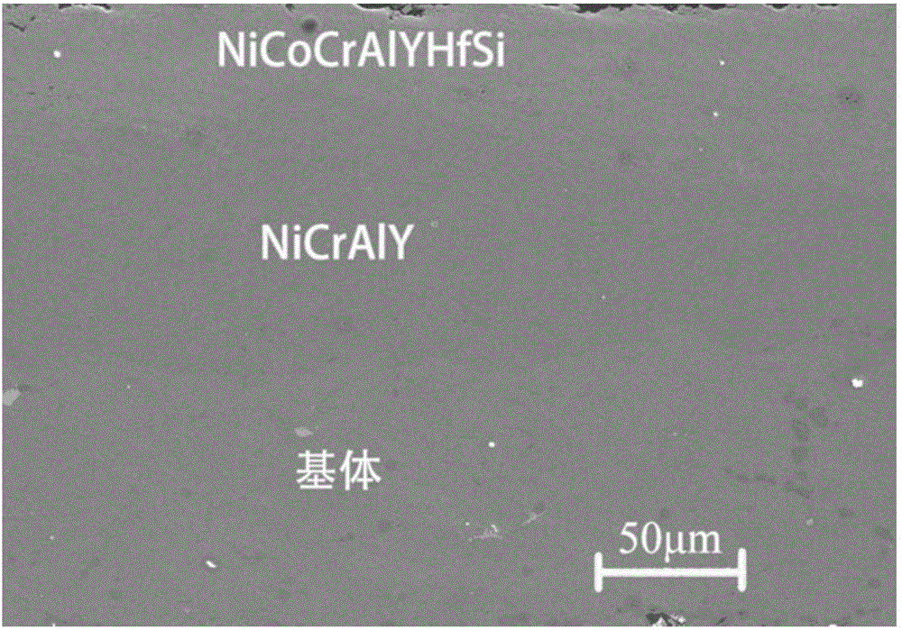
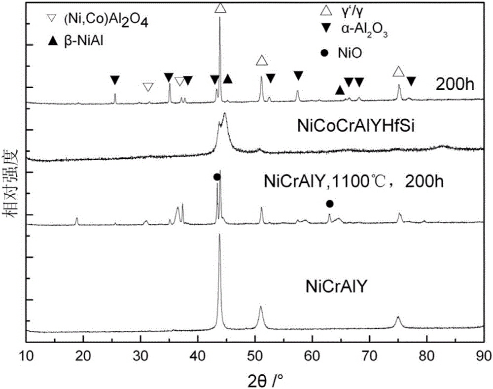
Bilayer-structure bonding coating on surface of single crystal alloy and preparation method of bilayer-structure bonding coating
A double-layer structure and bonding layer technology, applied in metal material coating process, coating, melt spraying and other directions, can solve the complex composition and performance regulation of bonding layer, high cost, and the influence of the interface bonding performance of the barrier diffusion layer. and other problems, to achieve good high temperature oxidation resistance, low cost, and improve the effect of high temperature oxidation resistance
- Summary
- Abstract
- Description
- Claims
- Application Information
AI Technical Summary
Problems solved by technology
Method used
Image
Examples
Embodiment 1
[0071] Example 1: Preparation of double-layer structure bonding layer on the surface of DD6 single crystal alloy
[0072] Step 1: Prepare the DD6 single crystal alloy matrix material, clean it with anhydrous acetone, use a suction sandblasting machine at 0.1Mpa sandblasting gas pressure to perform sandblasting on the sprayed surface, and then use compressed air to blow away the surface residue The sand particles are cleaned again with anhydrous acetone, the substrate is installed on the tooling, and it is to be sprayed.
[0073] Step 2: Put the dried Ni26Cr4Al0.4Y (here abbreviated as 100% of total weight, 0.4% of Y, 4% of Al, 26% of Cr, the rest is Ni", the following abbreviation will be the same Method, no more details) and Ni20Co18Cr12Al0.7Y0.5Hf0.1Si bonding layer powder are put into the powder feeder respectively.
[0074] Step 3: Turn on the oxygen-kerosene supersonic flame spraying equipment, the spraying process parameters are:
[0075] Oxygen flow rate: 38m 3 / h;
[0076] Ker...
Embodiment 2
[0084] Example 2: Preparation of a double-layer structure bonding layer on the surface of IC10 single crystal alloy
[0085] The first step: prepare IC10 single crystal alloy matrix material, clean with anhydrous acetone, use suction sandblasting machine at 0.15Mpa sandblasting gas pressure to perform sandblasting roughening treatment on the sprayed surface, and then use compressed air to blow away the surface residue The sand particles are cleaned again with anhydrous acetone, the substrate is installed on the tooling, and it is to be sprayed.
[0086] Step 2: Put the dried Ni24Cr6Al0.7Y and Ni24Co15Cr13Al0.1Y0.5Hf0.5Si bonding layer powders into the powder feeder respectively.
[0087] Step 3: Turn on the oxygen-kerosene supersonic flame spraying equipment, the spraying process parameters are:
[0088] Oxygen flow rate: 45m 3 / h;
[0089] Kerosene flow rate: 20m 3 / h;
[0090] Carrier gas flow: 0.8m 3 / h;
[0091] Powder feeding rate: 80g / min;
[0092] Swing speed of spray gun: 1000mm / s...
Embodiment 3
[0097] Example 3: Preparation of double-layer structure bonding layer on the surface of IC10 single crystal alloy
[0098] The first step: prepare IC10 single crystal alloy matrix material, clean with anhydrous acetone, use suction sandblasting machine at 0.15Mpa sandblasting gas pressure to perform sandblasting roughening treatment on the sprayed surface, and then use compressed air to blow away the surface residue The sand particles are cleaned again with anhydrous acetone, the substrate is installed on the tooling, and it is to be sprayed.
[0099] Step 2: Put the dried Ni25Cr5Al0.6Y and Ni22Co16Cr11Al1Y0.1Hf0.5Si bonding layer powders into the powder feeder respectively.
[0100] Step 3: Turn on the oxygen-kerosene supersonic flame spraying equipment, the spraying process parameters are:
[0101] Oxygen flow rate: 40m 3 / h;
[0102] Kerosene flow rate: 17m 3 / h;
[0103] Carrier gas flow: 0.5m 3 / h;
[0104] Powder feeding rate: 60g / min;
[0105] Swing speed of spray gun: 800mm / s.
[0...
PUM
| Property | Measurement | Unit |
|---|---|---|
| Thickness | aaaaa | aaaaa |
| Thickness | aaaaa | aaaaa |
| Thickness | aaaaa | aaaaa |
Abstract
Description
Claims
Application Information
 - R&D
- Intellectual Property
- Life Sciences
- Materials
- Tech Scout
- Unparalleled Data Quality
- Higher Quality Content
- 60% Fewer Hallucinations
Browse by: Latest US Patents, China's latest patents, Technical Efficacy Thesaurus, Application Domain, Technology Topic, Popular Technical Reports.
© 2025 PatSnap. All rights reserved.Legal|Privacy policy|Modern Slavery Act Transparency Statement|Sitemap|About US| Contact US: help@patsnap.com


