
Simplified over-current detection circuit for high-side power tube

A high-end power tube, over-current detection technology, applied in the measurement of electrical variables, measurement of current/voltage, measurement devices, etc., can solve the problems of occupying a lot of chip area, poor accuracy, breakdown damage of high and low voltage circuits, etc. The effect of small area, chip cost saving, and convenient layout layout

Active Publication Date: 2016-09-21
杭州中科微电子有限公司
View PDF7 Cites 5 Cited by
  • Summary
  • Abstract
  • Description
  • Claims
  • Application Information

AI Technical Summary

Problems solved by technology

[0004] Since the size of the mirror tube is much smaller than the size of the power tube, the layout cannot be matched, and the drain-source voltage cannot be completely consistent, so there is a deviation in the mirror current
In the high / low voltage conversion process, there are process deviations and the comparator is offset, so the accuracy is relatively poor
At the same time, due to the complex structure of the current high-end power tube overcurrent detection circuit, which occupies a large chip area, the mixture of high and low voltage circuits is easy to cause breakdown damage and other problems.

Method used


Image

  • Simplified over-current detection circuit for high-side power tube
  • Simplified over-current detection circuit for high-side power tube

Examples


Embodiment Construction

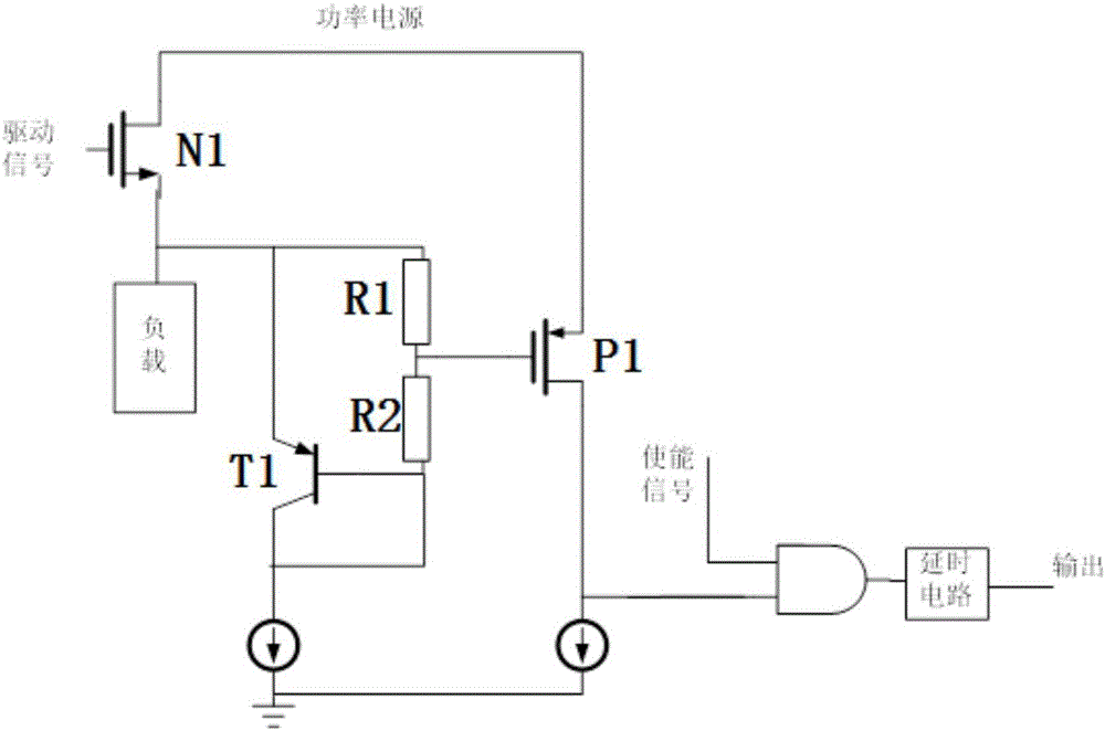
[0021] Such as figure 2 As shown, when the high-end power NMOS transistor N1 is normally turned on, the driving signal is generally higher than the power supply, the high-end power NMOS transistor N1 is in the linear region, and the conduction voltage drop is very small. , not enough to turn on the right switch tube P1. As the current flowing through the load increases, the drain-source voltage drop of the power transistor N1 increases, and the source terminal voltage decreases. When the load current value reaches a certain value, the source terminal voltage is divided by the resistor (the first The resistance ratio between the resistor and the second resistor is adjustable), which can make the right switch tube P1 turn on, the current flowing through the P1 tube is greater than the current provided by the current source, and output a high level to the AND gate. The other input enable signal of the AND gate is synchronized with the drive signal of the power transistor. When ...


PUM


Abstract

The invention discloses a simplified over-current detection circuit for a high-side power tube. The simplified over-current detection circuit comprises a high-side power tube, a load, a transistor, a voltage-dividing resistor, a switching tube, a first tail current source and a second tail current source, a logic circuit and a delay circuit. The logic circuit is used for introducing an enabling signal. The high-side power tube is an NMOS tube; the triode is a PNP tube or an NPN tube; and the switching tube is a PMOS tube. The triode is configured to have a translation voltage; the logic circuit is an AND gate. When the switching tube is in conduction, a drain terminal high level is converted into a low level that is provided for the logic circuit. The load is an inductive load, a resistive load or a short-circuit grounding unit. The resistance proportion of the first resistor to the second resistor can be adjusted. The enabling signal and a drive signal of the high-side power tube are synchronous. According to the invention, detection of the current detection circuit becomes direct; no auxiliary device is needed; and the detection precision is high. Under the circumstance that the current detection precision is improved, the circuit structure become simple; easy adjusting is realized; the occupied chip area is small; the domain layout becomes convenient; the chip cost is saved; and easy transplanting is realized.

Description

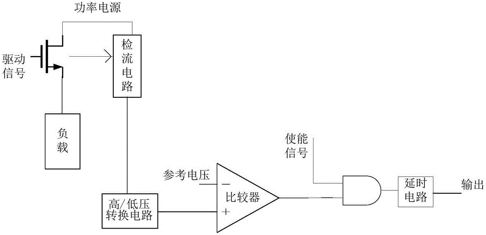
technical field [0001] The invention relates to the field of motor drive, in particular to a simplified high-end power tube overcurrent detection circuit and the detection of the high-end power tube current overcurrent value. Background technique [0002] The current high-end power tube overcurrent detection mainly uses the current detection circuit and the high / low voltage conversion circuit to convert the power tube current into a voltage signal to the ground in proportion, and then compares it with the reference voltage. The result of the comparison is passed through the AND gate and the delay circuit. , as the final output of the overcurrent detection circuit. When the drive signal of the power tube is high enough to turn on the high-end power N tube, the enable signal of the AND gate is also high; and when the drive signal is low, the signal of the AND gate is also low, such as figure 1 shown. [0003] The current detection circuit mainly mirrors the current of the po...

Claims


Application Information

Patent Timeline
Patent Type & Authority Applications(China)
IPC IPC(8): G01R19/165
CPCG01R19/16538
Inventor 夏存宝王良坤
Owner 杭州中科微电子有限公司
Learn More