Sintering clamp and sintering method for multiple tube cores of semiconductor laser in independent pressure-applying manner

A technology of pressure sintering and sintering method, which is applied in the direction of semiconductor lasers, lasers, laser parts, etc., can solve the problems of high manufacturing cost, damage, difficulty in processing and assembling precision parts, etc., and achieves high production efficiency, convenient operation, and structure. simple effect

Inactive Publication Date: 2016-09-21
HI TECH OPTOELECTRONICS
View PDF9 Cites 6 Cited by
  • Summary
  • Abstract
  • Description
  • Claims
  • Application Information

AI Technical Summary

Problems solved by technology

The disadvantage of this method is that only one laser can be sintered at a time, which is not suitable for batch sintering; and there are many parts in the whole device, it is difficult to process and assemble the precision parts required, and the manufacturing cost is high
The disadvantage of this method is that the magnetic force of the strip pressing block is used to exert pressure on multiple dies together, and the force of each die will be affected by other dies
In extreme cases, some dies are unstressed, resulting in pressureless sintering; some dies will be overstressed, resulting in damage

Method used


Image

  • Sintering clamp and sintering method for multiple tube cores of semiconductor laser in independent pressure-applying manner
  • Sintering clamp and sintering method for multiple tube cores of semiconductor laser in independent pressure-applying manner

Examples


Embodiment Construction

[0025] Embodiments of the present invention will be further described below in conjunction with the accompanying drawings.

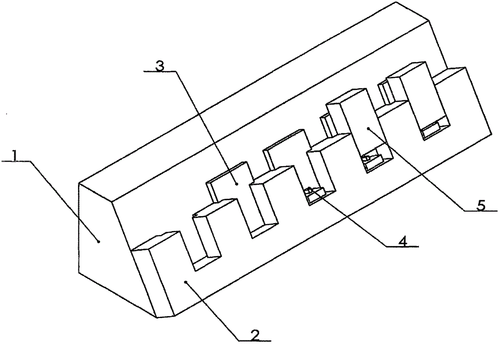
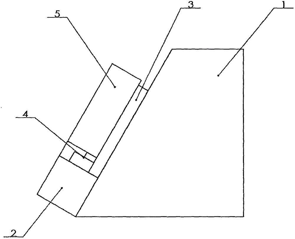
[0026] Please see attached figure 1 and attached figure 2 As shown, a semiconductor laser multi-die pressure sintering fixture includes a base 1, a fixed block 2, a block 3 and a pressing block 5, the longitudinal section of the base 1 is a trapezoidal structure, and the fixed block 2 It is fixed on the slope surface of the base 1 by threading or welding; more than 2 grooves can be opened on the fixed block 2, and each groove is in contact with the slope surface of the base 1 And a card slot is provided inside, and the blocking piece 3 is fitted in the groove along the slope surface of the base 1, and is fixed by the card slot, and each of the grooves corresponds to One of the briquetting blocks 5 .

[0027] The longitudinal section of the base 1 is a right-angled trapezoidal structure, and the fixing block 2 is perpendicular to the slope surface of ...


PUM


Abstract

The invention discloses a sintering clamp and a sintering method for multiple tube cores of a semiconductor laser in an independent pressure-applying manner. The sintering clamp comprises a base, fixed blocks, baffle sheets and pressing blocks, wherein the longitudinal section of the base adopts a trapezoidal structure; the fixed blocks are fixed on the slope surface of the base through screw threads or welding; more than two grooves are formed in the fixed blocks; each groove is in contact with the slope surface of the base, and a clamping groove is formed in each groove; the baffle sheets are adapted in the grooves along the slope surface of the base, and are fixed through the clamping grooves; and each groove is corresponding to one pressing block. The sintering clamp is simple in structure, convenient to operate, low in cost, capable of sintering under nitrogen atmosphere protection, and capable of preventing soldering flux from being oxidized in high-temperature sintering; a mode of pressure applying through gravity is adopted, so that the condition of damage to the clamp caused by a spring or an elastic sheet is avoided; in addition, the each tube core can be applied with pressure independently in a batch manner; the tube cores are not affected each other; and therefore, the rapid and batch sintering for the tube cores and heat sinks of the semiconductor laser in the independent pressure-applying manner can be realized, and high production efficiency is achieved as well.

Description

technical field [0001] The invention relates to a sintering jig of a semiconductor laser, in particular to a multi-core semiconductor laser sintering jig for separately pressurized sintering and a sintering method thereof, belonging to the technical field of semiconductor laser sintering. Background technique [0002] With the progress of society and the development of science and technology, the status of semiconductor lasers will become more and more prominent, and their applications will become more and more extensive. In particular, its wide wavelength range, small size, light weight, long life and many other advantages have been widely used in lighting, projection, communication, medical, military and scientific research and other fields. Such as optical fiber communication, laser ranging, material processing, laser guidance, etc. Due to the characteristics of small size and high power of the die of the semiconductor laser, the heat dissipation of the die is relatively...

Claims


Application Information

Patent Timeline
Patent Type & Authority Applications(China)
IPC IPC(8): H01S5/022H01S5/024
CPCH01S5/02469H01S5/0237
Inventor 梅石磊佟海保刘迪黎磊孙海东王晓薇
Owner HI TECH OPTOELECTRONICS
Why Eureka
Try Eureka