A Multi-element Diode Capacitor Network and Coupled Inductor High Gain DC Converter

A technology of diode capacitance and coupled inductance, which is applied in the field of distributed power generation, can solve the problems of increasing device loss, large inrush current, and high voltage gain, and achieve the effects of reducing switching loss, reducing volume, and increasing voltage gain

Active Publication Date: 2017-12-15
邳州德好农产品加工有限公司
View PDF3 Cites 0 Cited by
  • Summary
  • Abstract
  • Description
  • Claims
  • Application Information

AI Technical Summary

Problems solved by technology

However, due to the influence of parasitic parameters in the inductance loop of the main circuit and the performance of the controller, even if the duty cycle reaches the limit state close to 1, it is difficult to have a high voltage gain
The diode conducts in a very short time and bears relatively large voltage and current stress, which will inevitably lead to serious switching loss and EMI problems
figure 1 (b) is a multi-unit diode-capacitor network high-gain DC converter. When S=ON, the two capacitors in unit 1 are connected in series to charge the two capacitors in unit 2, and multiple capacitors with voltage source characteristics directly pass through the power The short-circuit charging and discharging process of the semiconductor device produces a huge inrush current, which increases the loss of the device

Method used


Image

  • A Multi-element Diode Capacitor Network and Coupled Inductor High Gain DC Converter
  • A Multi-element Diode Capacitor Network and Coupled Inductor High Gain DC Converter
  • A Multi-element Diode Capacitor Network and Coupled Inductor High Gain DC Converter

Examples


Embodiment Construction

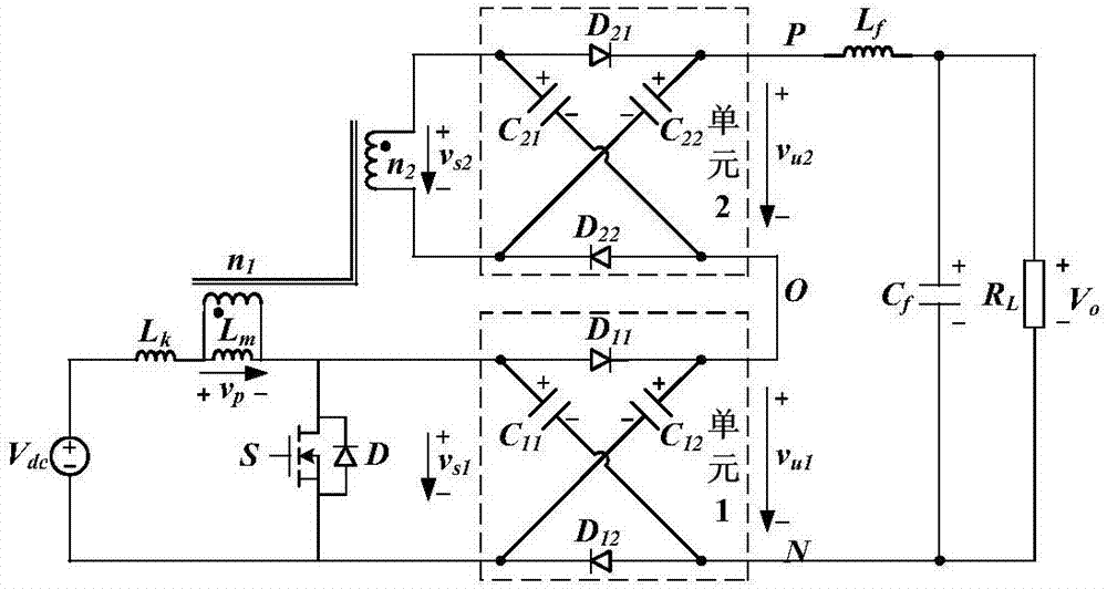
[0023] The present invention is described in further detail below in conjunction with accompanying drawing:

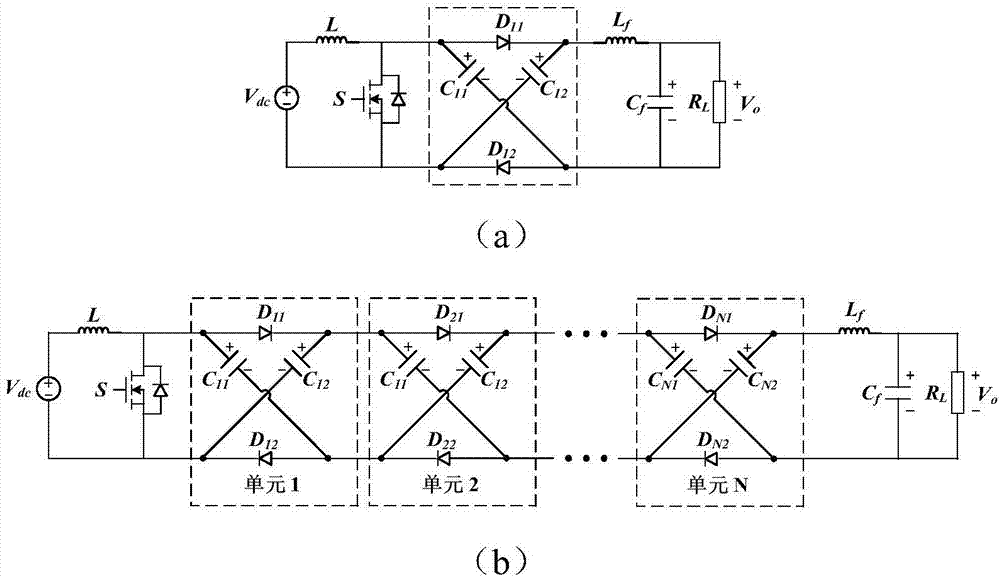
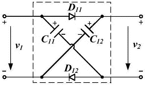
[0024] see image 3 with Figure 4 , the present invention includes the input power supply V dc , controllable switch tube S, multi-winding coupled inductor, multiple two-port diode capacitor boost units, LC filter circuit and output load R L ; where the coupled inductance can be equivalent to an ideal transformer with a fixed ratio and a magnetizing inductance L m After parallel connection, it is equivalent to the leakage inductance L of the primary side k series; LC filter circuit consists of filter inductor L f and filter capacitor C f Composition; the two-port diode capacitor boost unit includes a first diode D 11 , the second diode D 12 , the first DC capacitor C 11 and a second DC capacitor C 12 ; The first DC capacitor C 11 The anode of the first diode D 11 anode of the second DC capacitor C 12 The anode of the first diode D 11 The cathode; the firs...


PUM


Abstract

The invention discloses a multi-unit diode capacitor network and a coupled inductor high-gain DC converter. The main circuit topology fully combines the characteristics of the multi-winding coupled inductor and the diode capacitor boost network, and has the following obvious advantages: 1) Increase the voltage gain, reduce the Voltage stress of power devices; 2) Realize zero output voltage ripple, significantly reducing the demand for LC filters; 3) Reduce the turns ratio of coupled inductors, reduce the volume of magnetic components, and increase power density; 4) Suppress the turn-off voltage of switching tubes peak, reduce switching loss, and improve power conversion efficiency; 5) The basic step-up unit is modularly designed, with strong flexibility; the invention has broad application prospects in new energy distributed power generation systems.

Description

【Technical field】 [0001] The invention belongs to the field of distributed power generation such as new energy photovoltaics and fuel cells, and relates to a high-gain DC conversion technology, in particular to a multi-unit diode capacitor network and a coupled inductor high-gain DC converter. 【Background technique】 [0002] The development and utilization of green energy such as solar energy and fuel cells has important strategic significance for optimizing my country's energy structure and achieving sustainable economic and environmental development. Different from traditional DC power sources, such as DC generators and storage batteries, photovoltaics and fuel cells have the characteristics of low output voltage and obvious voltage drop. One of the many technical bottlenecks in the system. [0003] Typical photovoltaic and fuel cell power generation systems are divided into two types: single-stage and two-stage. The single-stage structure inverter (DC-AC) only undergoes...

Claims


Application Information

Patent Timeline
Patent Type & Authority Patents(China)
IPC IPC(8): H02M3/07H02M1/14
CPCH02M1/14H02M3/07H02M1/0054H02M1/0077Y02B70/10
Inventor 张岩董卓刘进军马小龙李伟强
Owner 邳州德好农产品加工有限公司
Why Eureka
Try Eureka