LDO (Low Drop-out voltage regulator) overshooting protection circuit

A protection circuit and overshoot technology, applied in the field of electronics, can solve the problems of increasing LDO power consumption, complex circuit structure, and difficulty in establishing quickly, and achieve the effects of increasing chip complexity, simple circuit structure, and increasing reliability.

Active Publication Date: 2016-10-05
HI TREND TECH SHANGHAI
View PDF6 Cites 19 Cited by
  • Summary
  • Abstract
  • Description
  • Claims
  • Application Information

AI Technical Summary

Problems solved by technology

However, this technical solution requires a lot of additional device circuits. At the same time, if the power-on is faster, the speed of the comparator needs to be very fast, which increases the power consumption of the LDO. At the same time, a quick-start reference circuit and corresponding control circuit are additionally required. The circuit structure is complex, and with this architecture, in some cases of fast power-on (such as below the us level), the second reference voltage circuit is also difficult to establish quickly, so that it cannot well eliminate the overshoot when the LDO is powered on. rush
[0005] The prior art also discloses a LDO overshoot protection circuit (CN203102064U), such as figure 2 As shown, an RC delay circuit and pull-up PMOS transistor M3 are added to the LDO circuit to control the gate of the power transistor M0. However, this protection circuit can eliminate overshoot for fast power-up, but for medium-speed power-up and slow Power-on (especially output hundreds of mA current or no external large-capacitance LDO), this protection circuit cannot effectively eliminate overshoot

Method used


Image

  • LDO (Low Drop-out voltage regulator) overshooting protection circuit
  • LDO (Low Drop-out voltage regulator) overshooting protection circuit
  • LDO (Low Drop-out voltage regulator) overshooting protection circuit

Examples


specific Embodiment

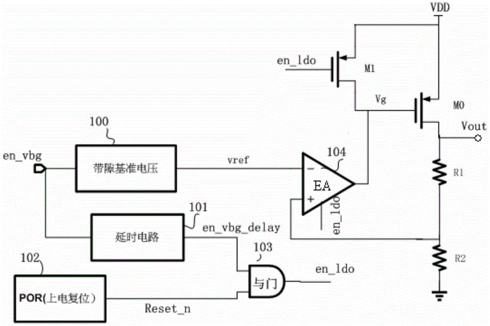
[0077] In a specific embodiment, the output reference voltage Vref of the reference voltage circuit 100 is connected to the inverting input terminal (-) of the error amplifier 104, and the voltage feedback signal sampled from the output terminal Vout is connected to the non-inverting input terminal (+) of the error amplifier 104. , when the external enable signal en_vbg is at a high level, the reference voltage circuit 100 is turned on, and when the external enable signal en_vbg is at a low level, the reference voltage circuit 100 is turned off.

[0078] The external enable signal en_vbg is processed by the signal processing circuit to generate the enable control signal en_ldo. The external enable signal en_vbg outputs the delay signal en_vbg_delay through the delay circuit 101; the delay time is set after the establishment time of the reference voltage circuit 100, and a delay of tens of us is realized; it is ensured that the en_vbg_delay signal is high after the reference vol...


PUM


Abstract

The invention relates to an LDO (Low Drop-out voltage regulator) overshooting protection circuit. The LDO overshooting protection circuit comprises a first MOS (Metal Oxide Semiconductor) tube, a second MOS tube, an error amplifier and a signal processing circuit, wherein the first MOS tube is controllably connected between an input end and an output end and is used for providing driving current to the output end; the second MOS tube is controllably connected between the input end and a grid electrode of the first MOS tube in parallel under the action of an enabled control signal; the error amplifier is used for carrying out comparing amplification on a voltage feedback signal sampled from the output end and standard voltage under the action of the enabled control signal; the output end of the error amplifier is connected with a control end of the first MOS tube; and the signal processing circuit is used for generating the enabled control signal under the action of an external enabled control signal and a detection signal obtained by detecting the size of voltage accessed into the input end. By reasonably controlling a sequential starting process of each module in an LDO electrifying process and overshooting protection can be provided for an externally hung large-capacitor type LDO with large current output or a capacitor-free LDO in a relatively wide power supply electrifying time range.

Description

technical field [0001] The invention relates to the field of electronic technology, in particular to an LDO overshoot protection circuit. Background technique [0002] Consumer electronic products such as smart phones, tablet computers (PADs), notebook computers and other portable electronic products have become an indispensable part of people's daily life. The power management chips in various portable electronic products are responsible for the transformation, distribution and detection of electric energy and other power management roles play an important role. LDO (Low Drop-out voltage regulator, low dropout linear voltage regulator) has high noise and ripple suppression, and at the same time low power consumption, low voltage regulator, low circuit cost, occupying PCB (Printed Circuit Board, Many advantages such as small area of ​​printed circuit board) are more suitable choices in power management systems. LDO generates a stable low voltage through a wide input range ...

Claims


Application Information

Patent Timeline
Patent Type & Authority Applications(China)
IPC IPC(8): G05F1/56
Inventor 李发宁马侠
Owner HI TREND TECH SHANGHAI
Why Eureka
Try Eureka