
Method of manufacturing a semiconductor device

A conductor, negative technology, used in semiconductor/solid-state device manufacturing, photolithography process of pattern surface, instruments, etc., can solve problems such as reducing yield and reducing lithography

Active Publication Date: 2019-12-13
TAIWAN SEMICON MFG CO LTD
View PDF5 Cites 0 Cited by
  • Summary
  • Abstract
  • Description
  • Claims
  • Application Information

AI Technical Summary

Problems solved by technology

However, even negative tone development processes may still have disadvantages regarding depth of focus (DOF), line width roughness (LWR) or scum
These problems reduce lithography efficacy and can lead to reduced yield or even device failure
[0004] Thus, although existing negative-tone developing processes have been widely used for their intended use, they are not entirely satisfactory in all respects.

Method used


Image

  • Method of manufacturing a semiconductor device
  • Method of manufacturing a semiconductor device
  • Method of manufacturing a semiconductor device

Examples


Embodiment Construction

[0026] The following disclosure provides many different embodiments or examples for implementing different features of the present invention. The following disclosure describes specific examples of various components and their arrangements to simplify the description. Of course, these specific examples are not intended to be limiting. For example, if the disclosure describes that a first feature is formed on or over a second feature, it means that it may include an embodiment in which the above-mentioned first feature is in direct contact with the above-mentioned second feature, and may also include additional features. Embodiments in which a feature is formed between the first feature and the second feature such that the first feature and the second feature may not be in direct contact. In addition, the same reference signs and / or symbols may be reused in different examples in the following publications. These repetitions are for simplicity and clarity and are not intended ...


PUM


Abstract

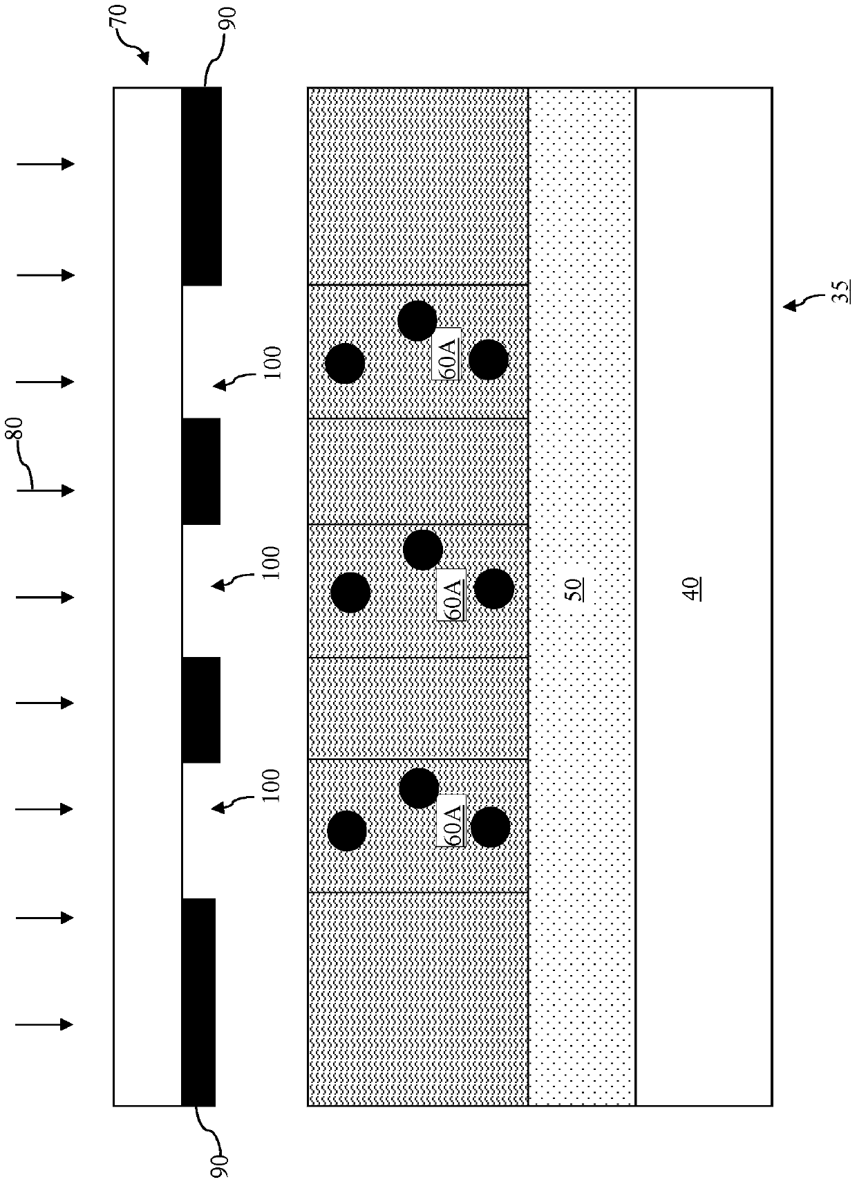
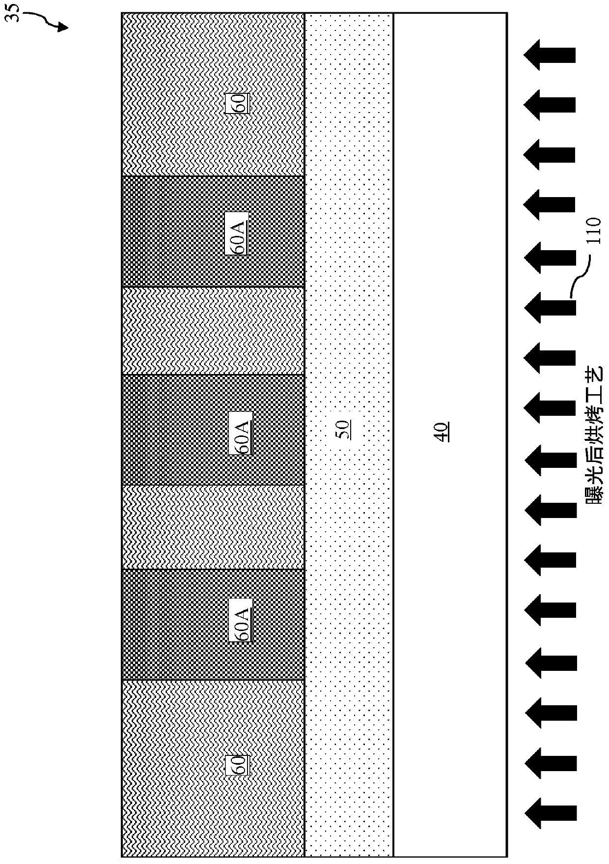
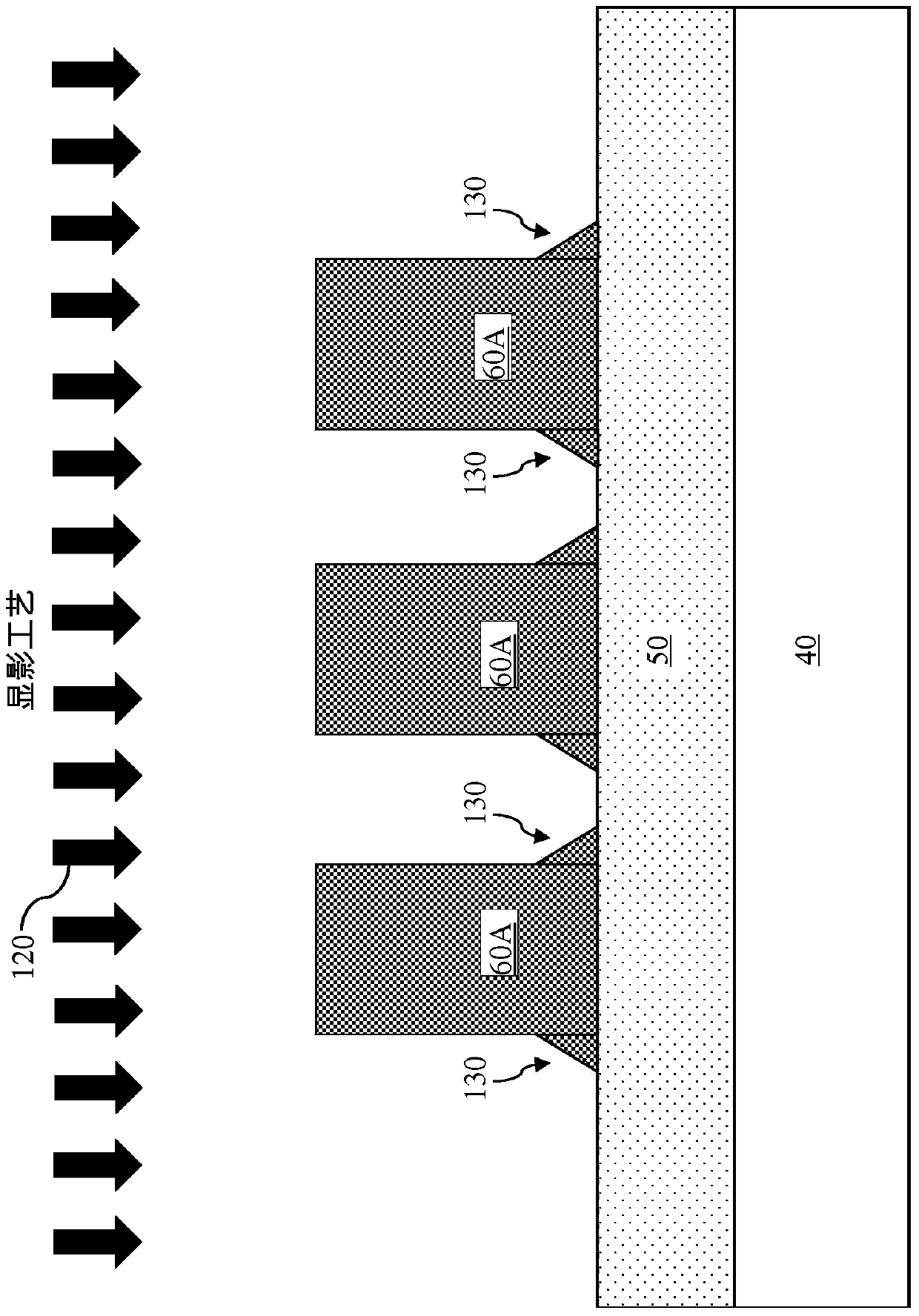
A material layer is formed over a substrate. A negative tone photoresist layer is formed over the material layer. An exposure process is performed to the negative tone photoresist layer. A post-exposure bake (PEB) process is performed to the negative tone photoresist layer. After the exposure process and the PEB process, the negative tone photoresist layer is treated with a solvent. The solvent contains a chemical having a greater dipole moment than n-butyl acetate (n-BA).

Description

technical field [0001] The present invention relates to a method of manufacturing a semiconductor device. Background technique [0002] The semiconductor integrated circuit (integrated circuit, IC) industry has experienced rapid growth. Technological advances in integrated circuit materials and design have resulted in generations of integrated circuits where each generation has smaller and more complex circuits than previous generations. However, these advances have increased the complexity of processing and manufacturing integrated circuits, and for these advances to be realized, similar developments are required in integrated circuit processing and manufacturing. In the course of integrated circuit development, functional density (i.e., the number of interconnected devices per wafer area) has broadly increased, while geometry size (i.e., the number of devices that can be The smallest member (or line) that is generated) has been reduced. [0003] As the size of semicondu...

Claims


Application Information

Patent Timeline
Patent Type & Authority Patents(China)
IPC IPC(8): H01L21/027G03F7/00G03F7/26
CPCG03F7/00G03F7/26H01L21/0274G03F7/0382G03F7/325G03F7/38G03F7/40
Inventor 赖韦翰张庆裕林进祥吴承翰王筱姗
Owner TAIWAN SEMICON MFG CO LTD
Learn More