Spirulina drying device
A drying device and technology of spirulina, applied in the directions of drying, drying machine, drying gas arrangement, etc., can solve the problems such as the quality decline of spirulina finished products, and achieve the effect of improving quality
- Summary
- Abstract
- Description
- Claims
- Application Information
AI Technical Summary
Problems solved by technology
Method used
Image
Examples
Embodiment 1
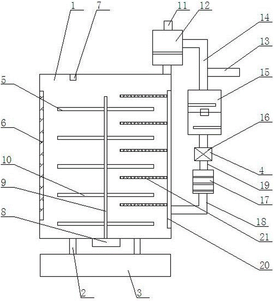
[0016] Such as figure 1 Shown, a kind of spirulina drying device comprises drying box 1, support frame 2, frame 3, circulating hot air device 4, and described drying box 1 is installed on frame 3 by lower end support frame 2; The right end of the drying box 1 is equipped with a circulating hot air device 4; the inner middle of the drying box 1 is equipped with a rotating spirulina shelf 5; Device temperature detector 7; described rotating spirulina placing frame 5 is made of rotating motor 8, rotating shaft 9, a plurality of meshed spirulina trays 10, and described rotating motor 8 is installed in the middle of the bottom of drying box 1, connected The internal rotating column of the drying box 1, a plurality of mesh spirulina trays 10 are installed at the left and right ends of the rotating shaft 9; an exhaust pipe 11 is installed on the right side of the top of the drying box 1, and a The filter cylinder 12 of built-in fiber cotton filter screen.
Embodiment 2
[0018] Such as figure 1 As shown, the circulating hot air device 4 is composed of a suction pipe 13, a circulation pipe 14, a heat sterilization box 15, a suction fan 16, a filter box 17, an air supply pipe 18, a connecting pipe 19, an air supply pipe 20, and a plurality of air outlets. The air duct 21 constitutes, the circulation duct 14 is installed on the top of the heating and sterilization box 15, the suction duct 13 is installed on the circulation duct 14, and the lower end of the heating and sterilization box 15 is connected to the suction fan 16 through the connecting pipe 19, so The lower end of the suction fan 16 is connected to the filter box 17 through the connecting pipe 19, the air supply pipe 18 is installed at the bottom of the filter box 17, and the other end of the air supply pipe 18 is connected to the air supply pipe 20, and the air supply pipe 20 is installed in the oven. On the right inner wall of the dry box 1, the air supply pipe 20 is a vertical pip...
Embodiment 3
[0020] Such as figure 1 As shown, the interior of the heating and sterilization box 15 is composed of a heating chamber and a sterilization chamber. The heating chamber and the sterilization chamber are connected through a ventilation pipe. Ozone sterilizer.
PUM
 Abstract
Description
Claims
Application Information
 - R&D
- Intellectual Property
- Life Sciences
- Materials
- Tech Scout
- Unparalleled Data Quality
- Higher Quality Content
- 60% Fewer Hallucinations
Browse by: Latest US Patents, China's latest patents, Technical Efficacy Thesaurus, Application Domain, Technology Topic, Popular Technical Reports.
© 2025 PatSnap. All rights reserved.Legal|Privacy policy|Modern Slavery Act Transparency Statement|Sitemap|About US| Contact US: help@patsnap.com

