

Method for quickly preparing rough laminar pyrolytic carbon
A rough layer, pyrolysis carbon technology, applied in the field of carbon materials, can solve the problems of uneven structure, slow cracking rate, uneven heating, etc., and achieve the effect of stable structure, lower production cost, and uniform structure
- Summary
- Abstract
- Description
- Claims
- Application Information
AI Technical Summary
Problems solved by technology
Method used
Image

Examples
Embodiment 1
[0049] This example provides a method for rapidly preparing pyrolytic carbon with a rough layer. The method comprises the steps of:
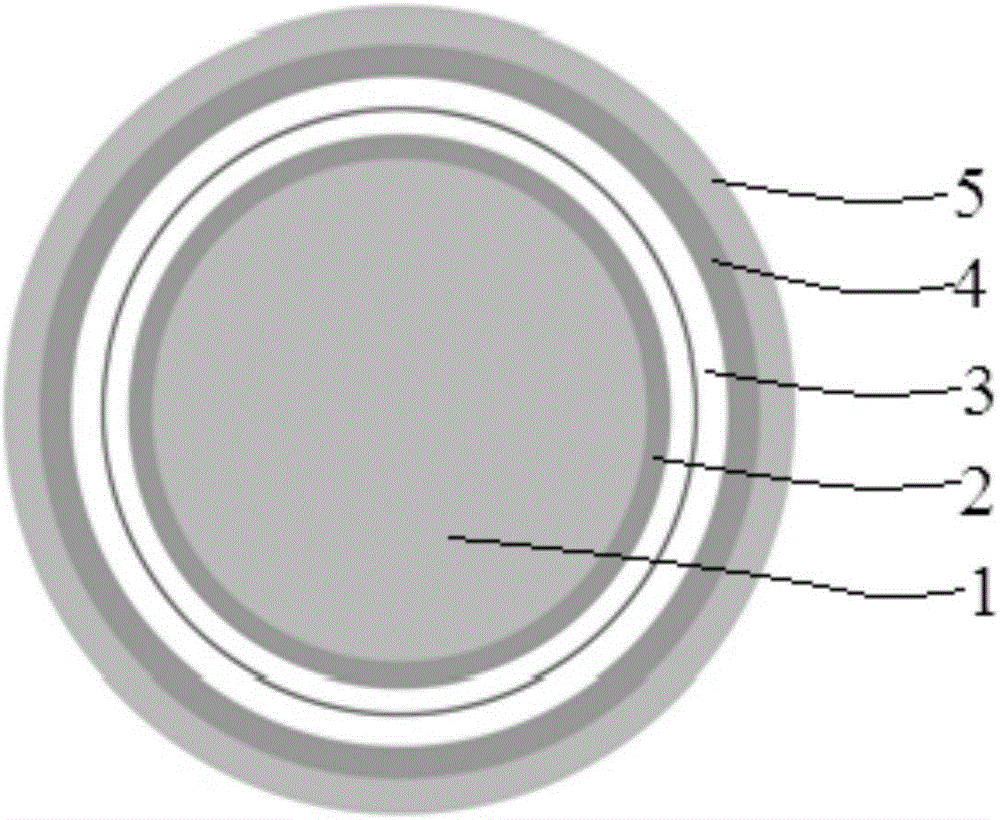
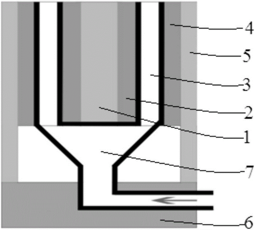
[0050] Microwaves are used to heat the preform and the silicon carbide tube at the same time, so that the temperature of the preform (that is, the temperature of the deposition area) is 1200° C., and the carbon source gas passing through the silicon carbide tube undergoes a cracking reaction, so that in A rough layer of pyrolytic carbon grows on the surface of the preform. Among them, the structure of the silicon carbide tube is as follows figure 1 , 2 As shown, in the direction extending from the central axis of the tube to the outer wall of the tube, the silicon carbide tube includes an insulating core layer, a first silicon carbide layer, a channel layer, a second silicon carbide layer and an insulating layer, and the first carbonized The silicon layer is sleeved on the surface of the insulating core layer, the insulating layer is sleeved ...
Embodiment 2
[0052] This example provides a method for rapidly preparing pyrolytic carbon with a rough layer. This method refers to the method in Example 1, except that the distance between the first silicon carbide layer and the second silicon carbide layer contained in the silicon carbide tube is 2 cm, and the distance in N 2 Natural gas is a carbon source gas, the carbon source mass concentration is 20-40%, the temperature of the deposition area is controlled at 1100°C, the vacuum degree of the system is 60KPa, the deposition time is 30 minutes, the thickness of the pyrolytic carbon reaches 24 microns, and the microstructure is rough layer structure, such as Figure 5 shown.
Embodiment 3
[0054] This example provides a method for rapidly preparing pyrolytic carbon with a rough layer. The method refers to the method in Example 1, except that the distance between the first silicon carbide layer and the second silicon carbide layer contained in the silicon carbide tube is 3 cm, and the distance in N 2 For diluting gas, methane is the carbon source gas, the carbon source mass concentration is 50-60%, the temperature of the deposition area is controlled at 1150°C, the vacuum degree of the system is 80KPa, the deposition time is 2 hours, the thickness of the pyrolytic carbon reaches 230 microns, and the microstructure is a rough layer structure, such as Figure 6 shown.
PUM
 Abstract
Description
Claims
Application Information