Retaining wall for water conservancy project

A technology for water conservancy projects and retaining walls, applied in the field of retaining walls, can solve the problems of long construction period, difficult water use, poor strength, etc., and achieve the effect of beautifying the city, preventing collapse and preventing slumps

Inactive Publication Date: 2016-10-12
TIANJIN UNIV
View PDF4 Cites 6 Cited by
  • Summary
  • Abstract
  • Description
  • Claims
  • Application Information

AI Technical Summary

Problems solved by technology

Existing retaining walls of water conservancy projects are often made of stones, which are weak in strength and have a long construction period. In addition, the retaining walls block the river, making it difficult to access water near the water

Method used


Image

  • Retaining wall for water conservancy project
  • Retaining wall for water conservancy project
  • Retaining wall for water conservancy project

Examples


specific Embodiment approach 1

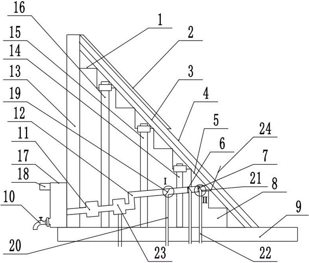
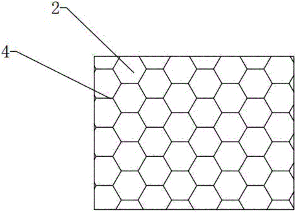
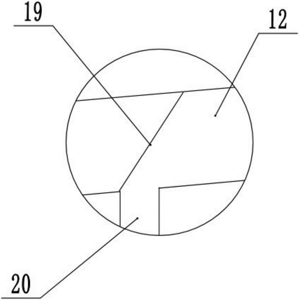
[0031] Combine below figure 1 , 2 , 3, 4, 5, 6, and 7 illustrate this embodiment. The present invention relates to a retaining wall, more specifically a retaining wall for water conservancy projects, including a prism shape 1, a greening layer 2, and an anti-corrosion layer 3 , steel wire protective net 4, plain concrete layer 5, sediment filter II 6, sediment filter I 7, slope body 8, foundation 9, faucet 10, river water purification filter 11, water pipe 12, concrete wall 13, high strength Bolt Ⅰ14, high-strength bolt Ⅱ15, high-strength bolt Ⅲ16, water tank 17, overflow pipe 18, baffle 19, sewage pipe Ⅰ20, sewage baffle 21, sewage pipe Ⅱ22, water purification device 23 and water guide 24, which can prevent moisture The land is eroded to prevent collapse and slumping, and the water pipes in the retaining wall can lead the river water out, and the water source can be directly used through the river water purification filter, which is convenient for pedestrians to use water. G...

specific Embodiment approach 2

[0041] Combine below figure 1 , 2 , 3, 4, 5, 6, and 7 illustrate this embodiment. This embodiment will further describe Embodiment 1. The angle between the water pipe 12 and the foundation 9 is an acute angle, and the water inlet end of the water pipe 12 is higher than the water outlet. . In this way, the water flow can flow out along the water pipe 12 under the action of gravity.

specific Embodiment approach 3

[0042] Combine below figure 1 , 2 , 3, 4, 5, 6, and 7 illustrate this embodiment. This embodiment will further illustrate Embodiment 1 or 2. The cross-sectional area of ​​the water pipe 12 is greater than all sewage pipes I20, sewage pipe II22 and drain pipe 23- The sum of the cross-sectional areas of 3. In this way, all the water in the water pipe 12 will not be discharged from the sewage pipe I20, the sewage pipe II22 and the drain pipe 23-3, and some clean water will still flow into the water tank 17.


PUM


Abstract

The invention relates to a retaining wall, specifically to a retaining wall for a water conservancy project, can prevent humid land from erosion and play the role of preventing collapse and a slump. A water pipe in the retaining wall can lead out river water, and a water source which can be directly used can be obtained by a river water purification filter, so that pedestrians can use water conveniently; and a greening layer is arranged on the retaining wall, thereby playing a role of beautifying a city. A concrete wall is built on the foundation, and a high-strength bolt I, a high-strength bolt II and a high-strength bolt III run through a slope and are arranged in the slope. A prismatic table structure is arranged on the surface of the slope, a plain concrete layer covers on the surface of the prismatic table structure, an anticorrosion layer is arranged on the plain concrete layer, a steel wire slope protection net covers on the surface of the anticorrosion layer, and greening layers are planted in meshes of the steel wire slope protection net. The water pipe is arranged in the slope, one end of the water pipe is provided with a sediment filter screen II and a sediment filter screen I, the other end of the water pipe is provided with a water tank and a faucet, and the river water purification filter is arranged in the middle section of the water pipe.

Description

technical field [0001] The invention relates to a retaining wall, in particular to a retaining wall of a water conservancy project. Background technique [0002] The retaining wall has the advantages of low cost, simple structure, small footprint and convenient construction, so the retaining wall is widely used in water conservancy projects. The retaining wall of a water conservancy project is a building with a strong slope. The natural soil river bank is prone to collapse due to the combined influence of various factors such as the seepage in the slope and the scour of the water flow in front of the slope. The retaining wall plays a role in preventing collapse and slide. effect. Existing retaining walls of water conservancy projects are often made of stones, which have poor strength and long construction period. In addition, the retaining walls block the river, making it difficult to access water near the water. So design a hydraulic engineering retaining wall. Contents...

Claims


Application Information

Patent Timeline
Patent Type & Authority Applications(China)
IPC IPC(8): E02B3/06E02B3/12E03B3/04E03B7/00E03B7/07
CPCE02B3/06E02B3/066E02B3/122E02B3/123E02B3/124E02B3/125E03B3/04E03B7/00E03B7/074
Inventor 卢陈涛
Owner TIANJIN UNIV
Why Eureka
Try Eureka