
Rainwater collection and utilization device

A technology of rainwater collection and rainwater, which is applied in water supply devices, drinking water devices, and general water supply conservation, etc., can solve the problem that the heat of rainwater cannot be effectively used, and achieve the effect of low energy consumption

Inactive Publication Date: 2016-10-12
HOHAI UNIV
View PDF8 Cites 9 Cited by
  • Summary
  • Abstract
  • Description
  • Claims
  • Application Information

AI Technical Summary

Problems solved by technology

[0005] However, the above-mentioned device is not suitable for removing the more seriously polluted rainwater produced during the initial rainfall, and the heat contained in the rainwater cannot be effectively utilized.

Method used


Image

  • Rainwater collection and utilization device
  • Rainwater collection and utilization device

Examples


Embodiment 1

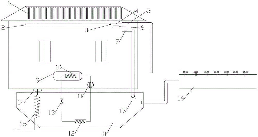
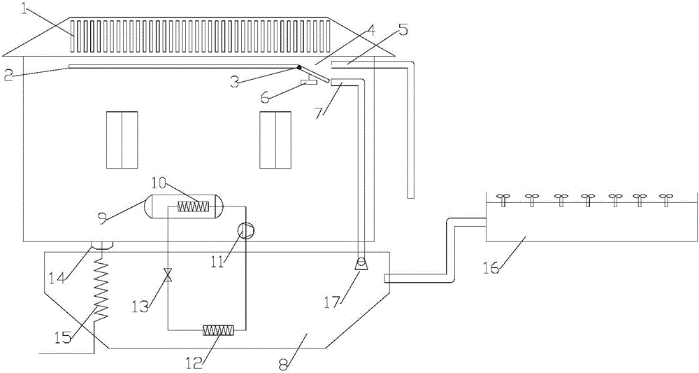
[0028] The rainwater utilization device provided by the invention is as figure 1 In the structure shown, a rain gutter 2 is installed on the house, and one end of the rain gutter 2 is connected to the rotating plate 4 through a torsion bar spring 3, and a water storage tank 6 is hung under the rotating plate 4. When the torsion bar spring 3 is in a natural state When the torsion bar spring 3 is compressed, the other end of the rotating plate 4 can be connected to the inlet of the sewage pipe 5; The collecting pipes 7 fit together; a rainwater storage tank 8 is arranged under the house, and the rainwater collecting pipe 7 is connected to the rainwater storage pond 8; a heat pump water heater 9 is arranged in the house, and a condenser 10 is arranged in the heat pump water heater 9, and the condenser One end of 10 is connected to the other end of condenser 10 through compressor 11, evaporator 12 and expansion valve 13, and evaporator 12 is arranged in rainwater storage tank 8; T...

Embodiment 2

[0037] The preparation method of the anticorrosion conductive paint coated on heat exchanger 15, the steps are as follows:

[0038] In parts by weight, 30-45 parts of modified epoxy resin, 40-50 parts of filler (mixture of glass powder, barium sulfate and titanium dioxide in a weight ratio of 4:2:2), additive BYK-180 1-3 parts of wetting and dispersing agent, 3-5 parts of pigment iron oxide red, 1-3 parts of surfactant octadecyl dimethyl benzyl ammonium chloride, 15-25 parts of organic solvent ethyl acetate, mix well, Then disperse evenly under the condition of rotating speed of 800-1500rpm, and get the coating after grinding;

[0039] The preparation method of the described modified epoxy resin comprises the following steps: Step 1, in parts by weight, 15 parts of maleic anhydride, 10 parts of hydroxypropyl acrylate, 6 parts of isooctyl acrylate, 1-tri- Mix 4 parts of fluoromethyl-1,3-butadiene and 3 parts of dicumyl peroxide uniformly as the first mixed liquid; mix 60 parts...


PUM


Abstract

The invention relates to a rainwater collection and utilization device. A rainwater groove is formed in a house; one end of the rainwater groove is connected to a rotary plate by virtue of a torsion rod spring; a water storage groove is hung on the lower part of the rotary plate; when the torsion rod spring is under a natural state, the other end of the rotary plate is attached to an inlet of a sewage pipe; a rainwater collection pipe is arranged below the sewage pipe; when the torsion rod spring is compressed, the other end of the rotary plate can be attached to the rainwater collection pipe; a rainwater storage pond is arranged below the house; the rainwater collection pipe is connected to the inside of the rainwater storage pond; a heat-pump water heater is arranged in the house; a condenser is arranged in the heat-pump water heater; one end of the condenser passes through a compressor, an evaporator and an expansion valve and is connected to the other end of the condenser; the evaporator is arranged in the rainwater storage pond; a heat exchanger is connected to the outlet of a drainage pipe in the house; and the heat exchanger is located in the rainwater storage pond. The rainwater utilization device provided by the invention can supply heat energy in rainwater so as to heat the interior of the house, and the rainwater utilization device is low in energy consumption.

Description

technical field [0001] The invention relates to a rainwater collection and utilization device, which belongs to the technical field of water conservancy equipment. Background technique [0002] According to statistics, nearly 400 of the more than 600 cities in the country are short of water or severely short of water. Especially in some large and super-large cities, the contradiction between supply and demand of water resources is more acute, which directly affects people's life, production and social development. The shortage of water resources has become one of the important factors affecting and restricting the sustainable development of my country's economy and society. With the rapid development of urbanization in my country, greater pressure will be placed on water resources and the water environment. Rainwater utilization is an effective measure to solve the contradiction between water shortage and economic and social development, alleviate the urban water crisis, a...

Claims


Application Information

Patent Timeline
IPC IPC(8): E03B3/02E04D13/04E03F5/10
CPCY02A20/108E03B3/02E03F5/10E04D13/04
Inventor 王雅华刘斯宏鲁洋沈超敏贾凡樊科伟徐思远
Owner HOHAI UNIV
Learn More