
Doppler anemometry laser radar radial wind speed real-time correction system

A Doppler wind measurement and laser radar technology, applied in the laser field, can solve problems such as wind speed is not strictly zero, interference, low signal-to-noise ratio, etc., to achieve the effect of improving accuracy and verifying accuracy

Active Publication Date: 2016-10-12
UNIV OF SCI & TECH OF CHINA
View PDF5 Cites 17 Cited by
  • Summary
  • Abstract
  • Description
  • Claims
  • Application Information

AI Technical Summary

Problems solved by technology

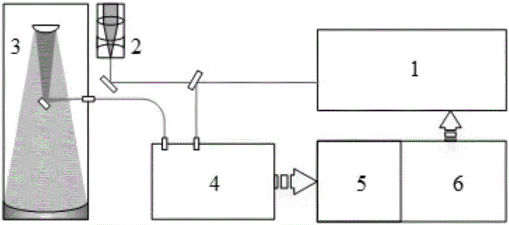
[0005] At present, there are several solutions to this radial deviation problem at home and abroad, but there are some problems: 1) A small part of the outgoing laser light is separated from the NASA wind lidar to couple it to the optical telescope, and then the optical fiber is coupled to the optical telescope. The receiver performs system zero-Doppler frequency calibration; this method can only collect data at one point, the signal-to-noise ratio is low, and stray scattered light from the telescope tube wall will cause interference
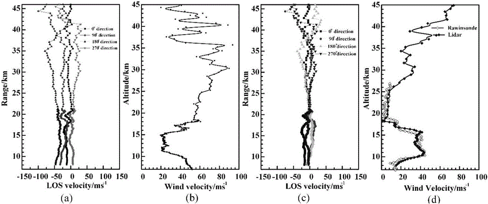
2) Domestic Ocean University of China’s wind-measuring lidar uses data in the vertical direction to calibrate the zero-Doppler frequency of the system. However, factual research has found that the wind speed in the vertical direction is not strictly zero. The sinking jet has a greater wind speed
However, the balloon data and the radar data cannot be synchronized in real time and the cost of launching the sounding balloon is too high, so using it to correct the radial wind speed of the system will have certain limitations

Method used


Image

  • Doppler anemometry laser radar radial wind speed real-time correction system
  • Doppler anemometry laser radar radial wind speed real-time correction system
  • Doppler anemometry laser radar radial wind speed real-time correction system

Examples


Embodiment Construction

[0024] The technical solutions in the embodiments of the present invention will be clearly and completely described below in conjunction with the accompanying drawings in the embodiments of the present invention. Obviously, the described embodiments are only some of the embodiments of the present invention, not all of them. Based on the embodiments of the present invention, all other embodiments obtained by persons of ordinary skill in the art without making creative efforts belong to the protection scope of the present invention.

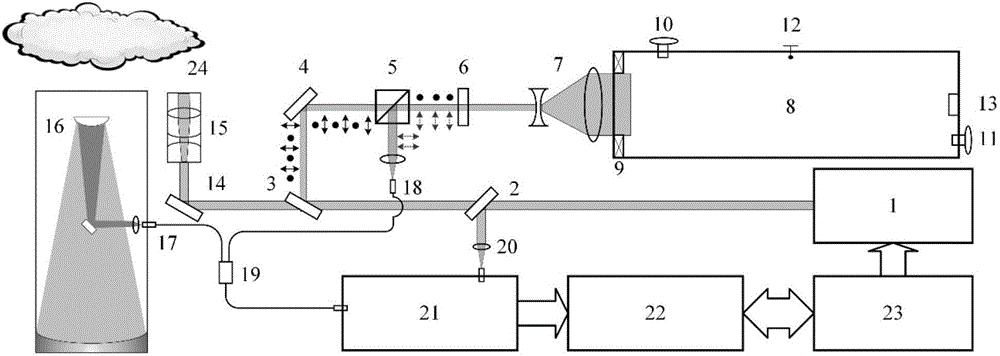
[0025] image 3 It is a schematic diagram of a real-time calibration system for Doppler wind lidar radial wind speed provided by an embodiment of the present invention. Such as image 3 As shown, it mainly includes:

[0026] Laser 1, first optical beam splitter 2, second optical beam splitter 3, first mirror 4, polarization beam splitter cube 5, 1 / 4 wave plate 6, first optical beam expander system 7, controllable atmospheric environment 8. Secon...


PUM

PropertyMeasurementUnit
Center wavelengthaaaaaaaaaa

Abstract

The invention discloses a Doppler anemometry laser radar radial wind speed real-time correction system. A very small part of laser is split in the system, and is couple to a self-built controllable atmospheric environment through a polarization coaxial optical path. An atmospheric echo signal in the environment is detected. A Doppler anemometry laser radar frequency discrimination system and a data acquisition system are used to inverse a measurement value in the state. At the same time, most of the laser is emitted to natural atmosphere. The echo signal is used to inverse the radial wind speed of natural atmosphere. The difference between the measurement value and the radial wind speed of natural atmosphere is true radial wind speed. According to the invention, the self-built atmospheric environment is controllable; the polarization coaxial optical path eliminates the influence of geometric factors; the system has a real-time calibration function; and the measurement accuracy of a Doppler anemometry laser radar is improved.

Description

technical field [0001] The invention relates to the field of laser technology, in particular to a real-time calibration system for Doppler wind measuring lidar radial wind speed. Background technique [0002] Atmospheric wind field is one of the important parameters in the research of atmospheric dynamics and climate meteorology. The information of wind field with high temporal and spatial resolution can be used to improve the atmospheric motion model and improve the accuracy of numerical weather prediction. The wind field information below the atmospheric boundary layer can also serve the fields of civil aviation, wind power generation, national defense and military affairs, and the wind field information extending from the troposphere to the stratosphere can be used to study atmospheric dynamics, observe the transmission, fragmentation process and fragmentation of atmospheric gravity waves The effect on the background wind field afterwards. Therefore, accurate measurement...

Claims


Application Information

Patent Timeline
IPC IPC(8): G01S17/88G01P5/00
CPCG01P5/00G01S17/88
Inventor 舒志峰窦贤康夏海云薛向辉谷升阳
Owner UNIV OF SCI & TECH OF CHINA
Learn More