
Permanent magnet biased five-degree-of-freedom integrated magnetic suspension supporting system

A permanent magnet bias and support system technology, applied in the field of bearing manufacturing, can solve the problems of limiting the application field of the magnetic levitation support system, low critical speed of the levitation support system, complex system structure and control, etc., to achieve easy manufacturing and assembly, simple structure , The effect of low power consumption

Active Publication Date: 2016-10-26
HUAIYIN INSTITUTE OF TECHNOLOGY
View PDF6 Cites 16 Cited by
  • Summary
  • Abstract
  • Description
  • Claims
  • Application Information

AI Technical Summary

Problems solved by technology

However, the existing five-degree-of-freedom magnetic levitation support systems all use multiple independent axial single-degree-of-freedom magnetic bearings, radial two-degree-of-freedom magnetic bearings, or radial-axial three-degree-of-freedom magnetic bearing units. The positions are combined into a five-degree-of-freedom magnetic levitation support system, resulting in a longer axial length, low critical speed of the levitation support system, low output power, and complex system structure and control, which limit the application fields of the excellent characteristics of the maglev support system

Method used


Image

  • Permanent magnet biased five-degree-of-freedom integrated magnetic suspension supporting system
  • Permanent magnet biased five-degree-of-freedom integrated magnetic suspension supporting system

Examples


Embodiment Construction

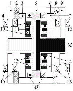
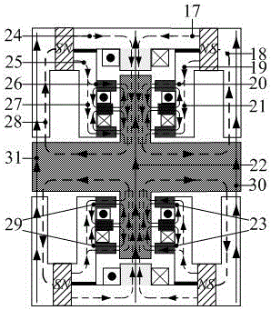
[0025] The present invention is based on the principle that two axially magnetized left annular permanent magnets 2 and right annular permanent magnet 8 provide bias magnetic flux to the five-degree-of-freedom integrated magnetic levitation support system, that is, the left radial magnetic bearing Left radial bias flux 28, left axial bias flux 26 and 27, right radial bias flux 18, right axial bias flux 20 and 21, radial bias flux 17 and 24; the left radial control winding 15 produces the left radial control magnetic flux 31, interacts with the left radial bias magnetic flux 28 to generate the left radial levitation force; the right radial control winding 16 produces the right The side radial control magnetic flux 30 interacts with the right radial bias magnetic flux 18 to generate the right radial levitation force; the axial control winding 13 generates the left axial control magnetic flux 29 and the right axial control magnetic flux respectively Through 23, the left axial con...


PUM


Abstract

The invention discloses a permanent magnet biased five-degree-of-freedom integrated magnetic suspension supporting system. A stator comprises a left side radial magnetic bearing iron core, a right side radial magnetic bearing iron core, a left side annular permanent magnet, a right side annular permanent magnet, a left side axial control iron core and a right side axial control iron core; a radial control iron core is arranged between the left side annular permanent magnet and the right side annular permanent magnet; a radial control winding is wound on stator teeth; a right side magnetism dividing aluminum ring is arranged between the left side axial control iron core and the radial control iron core, and a left side magnetism dividing aluminum ring is arranged between the right side axial control iron core and the radial control iron core; a left side radial control winding is correspondingly wound on the left side radial magnetic bearing iron core in a stator groove, and a right side radial control winding is correspondingly wound on the right side radial magnetic bearing iron core in the stator groove; and the left side axial control iron core and the right side axial control iron core are each of an E-shaped structure, and axial control windings are correspondingly wound in the stator groove. The supporting system is small in axial length, high in critical rotating speed, simple in structure, easy to manufacture and assemble, and capable of generating larger axial and radial suspension force, and the axial control magnetic flux and the radial control magnetic flux do not pass through the permanent magnets.

Description

technical field [0001] The invention relates to the technical field of bearing manufacturing, in particular to a bearing with short axial length, high critical speed, high utilization rate of iron core material, simple structure, manufacture and assembly, and neither axial nor radial control magnetic flux passes through permanent magnets, which can be used A low-power permanent magnet bias five-degree-of-freedom integrated magnetic levitation support system that generates greater axial and radial levitation forces. Background technique [0002] The magnetic levitation support system is a new type of high-performance support system that uses the electromagnetic force between the stator and the rotor to suspend the rotor in space, so that there is no mechanical contact between the stator and the rotor. Since there is no mechanical contact between the stator and the rotor, the rotor supported by the magnetic levitation system can reach a high operating speed, and has the advant...

Claims


Application Information

Patent Timeline
Patent Type & Authority Applications(China)
IPC IPC(8): F16C32/04
CPCF16C32/044F16C32/0465F16C32/0468F16C32/0489F16C2202/44
Inventor 张涛莫丽红张晨倪伟丁卫红叶小婷张惠萍
Owner HUAIYIN INSTITUTE OF TECHNOLOGY
Learn More