Method and apparatus for online test of laser damages of optical element

A technology for optical components and on-line testing, applied in measurement devices, fluorescence/phosphorescence, material analysis through optical means, etc., can solve the problem of difficult accurate positioning of damage morphology, lack of intuition and continuity, and in-depth study of damage evolution of optical components and lack of mechanisms

Inactive Publication Date: 2016-11-02
CHANGCHUN INST OF OPTICS FINE MECHANICS & PHYSICS CHINESE ACAD OF SCI
View PDF9 Cites 19 Cited by
  • Summary
  • Abstract
  • Description
  • Claims
  • Application Information

AI Technical Summary

Problems solved by technology

In the actual test, the differential interference microscopy method has the following two shortcomings: when the damage of the irradiation point of the sample is not obvious, its damage morphology is difficult to be accurately located in the off-line microscope; due to its relatively weak illumination intensity and the focus of the observation surface When the magnification exceeds 200 times, the clarity of microscopic imaging will degrade, making it difficult to observe and accurately judge the surface topography, and it is difficult to observe and distinguish smaller or weak damage topography
Although the change of damage threshold obtained by analyzing the above standards is helpful for analyzing the damage law of optical components, this method is a phase-only method, lacking intuition and continuity. There are obvious deficiencies in

Method used


Image

  • Method and apparatus for online test of laser damages of optical element
  • Method and apparatus for online test of laser damages of optical element

Examples


Embodiment Construction

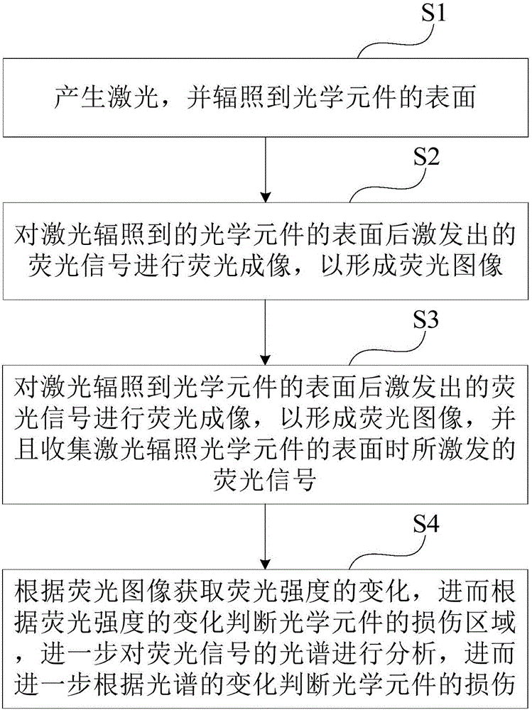
[0022] see figure 1 , figure 1 It is a flow chart of an online method for testing laser damage of an optical element provided by an embodiment of the present invention. like figure 1 As shown, the method of the present embodiment includes the following steps:

[0023] Step S1: Generate laser light and irradiate the surface of the optical element.

[0024] Step S2: performing fluorescence imaging on the fluorescence signal excited after the laser irradiates the surface of the optical element to form a fluorescence image.

[0025] Step S3: performing fluorescence imaging on the fluorescence signals excited after the laser irradiates the surface of the optical element to form a fluorescence image, and collecting the fluorescence signals excited when the laser irradiates the surface of the optical element.

[0026] Step S4: Obtain the change of the fluorescence intensity according to the fluorescence image, and then judge the damage area of ​​the optical element according to t...


PUM

PropertyMeasurementUnit
diameteraaaaaaaaaa

Abstract

The invention discloses a method and apparatus for online test of laser damages of an optical element. The method comprises the following steps: generating laser, and irradiating the surface of the optical element with the laser; carrying out fluorescence imaging on fluorescence signals excited after the irradiation of the surface of the optical element with the laser in order to form a fluoroscopic image, and collecting the fluorescence signals excited after the irradiation of the surface of the optical element with the laser; and obtaining the fluorescence intensity change according to the fluoroscopic images, judging the damage area of the optical element according to the fluorescence intensity change, analyzing the spectra of the fluorescence signals, and judging the damages of the optical element according to the spectrum change. The method and the apparatus, adopting the above mode, realize real-time online continuous monitoring of the irradiated area of the optical element, improve the damage evolution and the mechanism research efficiency of the optical element under the laser irritation condition, and are helpful for effectively researching the damage evolution and the mechanism of the optical element.

Description

technical field [0001] The invention relates to the field of laser damage and life testing of optical components, in particular to a method and device for online testing of laser damage of optical components. Background technique [0002] In recent years, the ArF excimer laser with a wavelength of 193nm has gained more and more attention in many fields including fine microprocessing of materials, deep ultraviolet lithography, material processing, laser marking, etc., excimer laser medical treatment and scientific research. The more widespread applications, especially in the field of photolithography preparation of very large scale integrated circuits, have very important social and economic value. It can be predicted that with the continuous development of related technologies, ArF excimer laser will surely gain greater application. [0003] Since 193nm is close to the forbidden band of most dielectric materials, the existence of intrinsic absorption, impurity absorption, a...

Claims


Application Information

Patent Timeline
Patent Type & Authority Applications(China)
IPC IPC(8): G01N21/64
CPCG01N21/6402G01N2021/6417
Inventor 邓文渊金春水靳京城李春周烽
Owner CHANGCHUN INST OF OPTICS FINE MECHANICS & PHYSICS CHINESE ACAD OF SCI
Why Eureka
Try Eureka