
3D navigation equipment for non-invasive real-time operation positioning

A navigation device and 3D technology, applied in surgical navigation systems, stereotaxic surgical instruments, computer-aided planning/modeling, etc., can solve the problems that laser devices cannot be replaced separately, have large errors, and cannot display the depth and position of lesions

Active Publication Date: 2016-11-09
HANGZHOU SANTAN MEDICAL TECH
View PDF6 Cites 22 Cited by
  • Summary
  • Abstract
  • Description
  • Claims
  • Application Information

AI Technical Summary

Problems solved by technology

[0005] In the previous research, we have applied for a number of patents on non-invasive real-time surgical positioning and navigation equipment, among which 201210385980.2 is named as an invention patent for a surgical positioning and navigation equipment attached to a C-arm X-ray machine. The image digitization frame and the simple laser emitting device and the image only perform simple linear processing, and the operator needs to manually control the image digitization frame through a hand-held remote control, so the invention cannot realize automatic calibration; the calibration process adopts manual acquisition of calibration point data method, the error is large; the laser device cannot be replaced separately and cannot guarantee that the outgoing light is coaxial with the laser tube and other defects
[0006] 201310515922.1, the invention patent named non-invasive real-time surgical positioning and navigation equipment has improved the above-mentioned defects, but it still can only generate two-dimensional images and cannot display the depth of the lesion. In order to improve the above-mentioned deficiencies, our previous research On the basis, the three-dimensional device is adapted, and the corresponding software is matched to realize the three-dimensional navigation with extremely low radiation

Method used


Image

  • 3D navigation equipment for non-invasive real-time operation positioning
  • 3D navigation equipment for non-invasive real-time operation positioning
  • 3D navigation equipment for non-invasive real-time operation positioning

Examples


Embodiment Construction

[0061] Below in conjunction with accompanying drawing, the present invention will be further described:

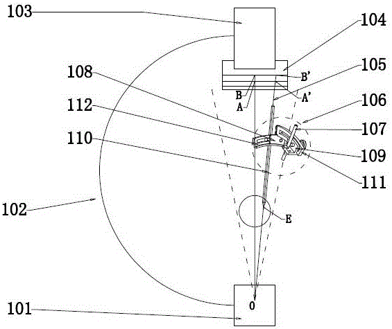
[0062] figure 1 It is a schematic diagram of the principle of the present invention; the physical phenomenon involved in the present invention has:

[0063] α. The imaging principle of C-arm X-ray machine 102 (C-arm machine) determines that its perspective area is conical (such as figure 1 Show);

[0064] β. The refractive index of X-rays in different media is ≈1, so X-rays propagate in a straight line in different media in the macroscopic state.

[0065] (1) According to the phenomenon α, assuming that we convert the perspective area into the following mathematical model, the conical shape can be split into countless coaxial and parallel concentric circles of different sizes, and one of the concentric circles is selected, and the longitude and latitude are used. Divide it into n small squares of equal size, and number them as (X, Y) according to certain rules;

[0066...


PUM


Abstract

The invention relates to 3D navigation equipment for non-invasive real-time operation positioning, which is characterized by comprising a laser positioning system and a space positioning device, wherein the laser positioning system is composed of a laser driving device, a work server, a digital signal shunt and a display, the laser driving device is in Bluetooth communication with the work server, and the work server, the digital signal shunt and the display are electrically connected; and the space positioning device is composed of a fixing slide rail, a two-way slide rail, a two-degree-of-freedom fixing slide block, a two-degree-of-freedom two-way slide block, a laser positioning rod and an operation channel which are mutually matched. According to the invention, path planning before an operation is realized through a computer, and an operation path can be spatially positioned accurately by visualized real-time registering of a focus point in the operation by the laser positioning system as well as the angle and depth control of the space positioning device; and the system is suitable for minimally-invasive orthopedic operations of any parts of patients.

Description

technical field [0001] The invention relates to a non-invasive real-time surgical positioning 3D navigation device. Background technique [0002] In orthopedic surgery, due to the narrow operating space and important tissues such as blood vessels and nerves around the bones, doctors cannot obtain a good view during the operation. The analysis and positioning of bones and lesions requires long-term experience accumulation of clinicians. Due to the inability to obtain precise positioning before surgery, traditional surgery requires a large incision for subsequent surgical operations, which is likely to cause massive intraoperative bleeding and cause damage to other tissues, increasing the risk of surgery. [0003] With the development of modern science and technology, the emergence of orthopedic surgical navigation technology has become an important auxiliary tool for surgery. Surgical navigation technology uses medical imaging equipment and computer image software to process ...

Claims


Application Information

Patent Timeline
IPC IPC(8): A61B34/20A61B34/10A61B90/13
Inventor 许硕贵何滨沈丽萍
Owner HANGZHOU SANTAN MEDICAL TECH
Learn More