Electric car heat management device

An electric vehicle and thermal management technology, applied in electric vehicles, electric power units, power units, etc., can solve problems such as inability to change the control mode, low energy utilization rate of thermal management systems, and energy waste.

Inactive Publication Date: 2016-11-09
天津中科先进技术产业有限公司
View PDF0 Cites 12 Cited by
  • Summary
  • Abstract
  • Description
  • Claims
  • Application Information

AI Technical Summary

Problems solved by technology

[0004] The present invention aims at the technical defects of the prior art, and provides an electric vehicle thermal management device to solve the technical problem of low energy utilization rate of the electric vehicle thermal management system in the prior art
[0005] Another technical problem to be solved by the present invention is that the thermal management system of electric vehicles in the prior art cannot change the control mode according to the environmental conditions, thus causing energy waste

Method used


Image

  • Electric car heat management device

Examples


Embodiment 1

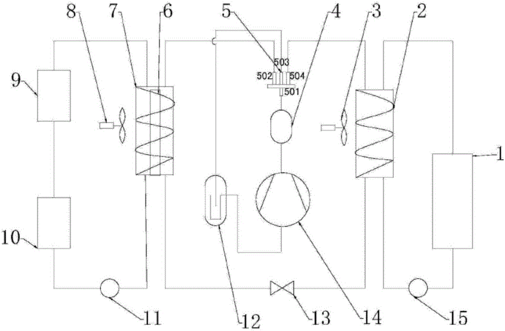
[0022] A heat management device for an electric vehicle, comprising a battery pack cooling jacket 1, a cabin heat exchanger 2, a second air-cooled radiator 3, an oil separator 4, an electromagnetic reversing valve 5, an electric heater 6, and a shell-and-tube heat exchanger Heater 7, first air-cooled radiator 8, motor cooling jacket 9, controller cooling jacket 10, first liquid pump 11, liquid collector 12, thermostat 13, air compressor 14, second liquid pump 15, wherein the electromagnetic reversing valve 5 includes a first port 501, a second port 502, a third port 503, and a fourth port 504. The outlet port of the air compressor 14 communicates with the inlet port of the oil separator 4, and the oil separator The outlet end of 4 communicates with the first port 501 of the electromagnetic reversing valve 5, and the second port 502, the third port 503, and the fourth port 504 of the electromagnetic reversing valve 5 are connected with the shell-and-tube heat exchanger 7 and the...

Embodiment 2

[0029] A heat management device for an electric vehicle, comprising a battery pack cooling jacket 1, a cabin heat exchanger 2, a second air-cooled radiator 3, an oil separator 4, an electromagnetic reversing valve 5, an electric heater 6, and a shell-and-tube heat exchanger Heater 7, first air-cooled radiator 8, motor cooling jacket 9, controller cooling jacket 10, first liquid pump 11, liquid collector 12, thermostat 13, air compressor 14, second liquid pump 15, wherein the electromagnetic reversing valve 5 includes a first port 501, a second port 502, a third port 503, and a fourth port 504. The outlet port of the air compressor 14 communicates with the inlet port of the oil separator 4, and the oil separator The outlet end of 4 communicates with the first port 501 of the electromagnetic reversing valve 5, and the second port 502, the third port 503, and the fourth port 504 of the electromagnetic reversing valve 5 are connected with the shell-and-tube heat exchanger 7 and the...


PUM


Abstract

The invention provides an electric car heat management device. The electric car heat management device is provided with a battery pack, a controller, a motor and a heat exchange channel between heat exchangers on the basis of a conventional heat management system, so that recycling and utilization of waste heat are achieved. Meanwhile, the working modes can be more flexibly switched according to the external environment by arranging two sets of heat exchanger loops, for example, as the high temperature tolerance of the battery pack is poor and the high temperature tolerance of the motor and the controller is good, the starting temperature of the second loop can be set to be the lower value, the starting temperature of the first loop can be set to be the higher value, and accordingly selective control is achieved, and the energy utilization rate is optimized. When the device operates, the first loop connected with a motor cooling jacket and a controller cooling jacket in series or the second loop connected with a battery pack cooling jacket in series is started, refrigerant fluid enters the heat exchangers from an air compressor through an oil separator, and cyclic heat exchange is achieved under driving of a liquid pump.

Description

technical field [0001] The invention relates to the technical field of electric vehicles, in particular to a heat management device for electric vehicles. Background technique [0002] An electric vehicle (BEV) refers to a vehicle that is powered by a vehicle-mounted power supply, drives the wheels with a motor, and meets the requirements of road traffic and safety regulations. Due to its smaller impact on the environment than traditional cars, its prospects are widely optimistic, but the current technology is still immature. Pure electric vehicles, compared with fuel vehicles, the main difference (difference) lies in the four major components, drive motor, speed controller, power battery, and on-board charger. Electric vehicles use fuel cells as the power source. The chemical reaction process of the battery will not produce harmful products, so the pollution of electric vehicles is extremely small. Since the energy conversion efficiency of the battery is 2 to 3 times highe...

Claims


Application Information

Patent Timeline
Patent Type & Authority Applications(China)
IPC IPC(8): B60L11/18B60K1/00B60K11/02
CPCB60K1/00B60K11/02B60K2001/005B60K2001/006B60L58/26Y02T10/70Y02T10/84
Inventor 吴正斌曹晓燕胡贺宾
Owner 天津中科先进技术产业有限公司
Why Eureka
Try Eureka