
Loose rock body drilling device and method

A drilling device and drilling location technology, applied in drilling equipment and methods, support devices, drilling equipment, etc., can solve problems such as difficulties in grouting drilling, reddening and softening of drill bits, and stuck drill, so as to avoid high temperature Steam injury accident, low cost, and the effect of ensuring safety

Active Publication Date: 2016-11-09
CCTEG CHINA COAL RES INST
View PDF4 Cites 0 Cited by
  • Summary
  • Abstract
  • Description
  • Claims
  • Application Information

AI Technical Summary

Problems solved by technology

This is mainly due to the loose body structure of the gangue, which is a porous medium, which is prone to drill sticking, hole collapse, and reddening and softening of the drill bit during drilling construction, making grouting drilling more difficult.
Therefore, the grouting drilling method needs to be improved urgently, but at present, there is no drilling method that can adapt to the loose rock mass structure and effectively improve the porosity rate and drilling efficiency.

Method used


Image

  • Loose rock body drilling device and method
  • Loose rock body drilling device and method

Examples


Embodiment 1

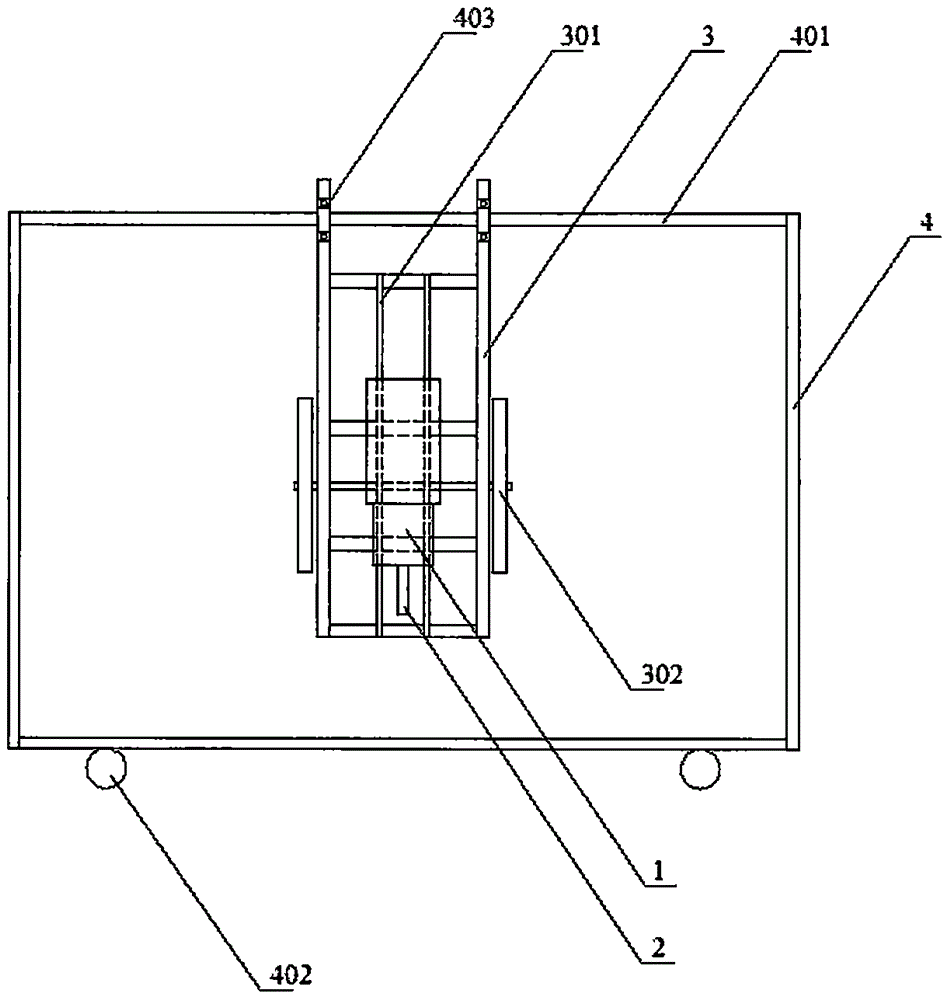
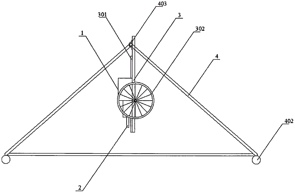
[0025] The loose rock drilling device includes a drilling rig 1, a drilling rod 2, a positioning vertical platform 3 and a support truss 4; the drilling machine 1 is fixed on the positioning vertical platform 3 together with the drilling rod 2, and the drilling rod 2 perpendicular to the ground; the positioning vertical platform 3 is fixed on the supporting truss 4; the positioning vertical platform 3 is equipped with a guide rail 301; the supporting truss 4 is a herringbone structure, including a beam 401, and rollers 402 are installed at the bottom , the beam 401 is used to fix the positioning stand 3, and the roller 402 is used to move the support truss 4, together with the drilling rig 1, to a predetermined position when the drilling rig 1 changes locations.

[0026] In this embodiment, the drilling machine 1 is a down-the-hole drilling machine.

[0027] In this embodiment, the roller 402 is a universal wheel.

[0028] The method for drilling in loose rock body using the ...

Embodiment 2

[0033] The loose rock drilling device includes a drilling rig 1, a drilling rod 2, a positioning vertical platform 3 and a support truss 4; the drilling machine 1 is fixed on the positioning vertical platform 3 together with the drilling rod 2, and the drilling rod 2 perpendicular to the ground; the positioning vertical platform 3 is fixed on the supporting truss 4; the positioning vertical platform 3 is equipped with a guide rail 301; the supporting truss 4 is a herringbone structure, including a beam 401, and rollers 402 are installed at the bottom , the beam 401 is used to fix the positioning stand 3, and the roller 402 is used to move the support truss 4, together with the drilling rig 1, to a predetermined position when the drilling rig 1 changes locations.

[0034] In this embodiment, the positioning stand 3 is also equipped with wheels 302, and the positioning stand 3 is connected to the support truss 4 through a connecting piece 403. After the operation of the drilling ...


PUM


Abstract

The invention provides a loose rock body drilling device. The loose rock body drilling device comprises a drilling machine, a drilling rod, a positioning vertical platform and a supporting truss; the drilling machine and the drilling rod are fixed on the positioning vertical platform and the drilling rod is vertical to the ground; the positioning vertical platform is fixed on the supporting truss; guide rails are mounted on the positioning vertical platform; under a working state of the drilling machine, the drilling machine does reciprocating motion on the guide rails; the supporting truss is of a herringbone shape and comprises a transverse beam; rolling wheels are mounted at the bottom of the supporting truss and the transverse beam is used for fixing the positioning vertical platform; and the rolling wheels are used for moving the supporting truss together with the drilling machine to a pre-set position when the drilling machine needs to work at other places. The loose rock body drilling device is simple in structure and easy to operate; and the problems that the drilling efficiency is low, the hole forming rate is low and the safety is poor when drilling and grouting work is carried out in a loose rock body can be effectively solved.

Description

technical field [0001] The invention relates to a drilling device and method, in particular to a drilling device and method suitable for loose rock mass. Background technique [0002] The high and steep gangue hills formed by the open-air accumulation of coal gangue not only occupy a large amount of land resources, pollute the surface and underground water sources, but also release a large amount of SO 2 , CO, H 2 Toxic and harmful gases such as S and benzo(a) castor cause air pollution and damage to the ecological environment, and may cause more destructive disasters such as water gas explosions, causing serious property losses and casualties. It is of great safety and economic significance to control gangue dumps and prevent spontaneous combustion of gangue dumps. [0003] At present, one of the more commonly used methods to prevent spontaneous combustion of gangue dumps is the grouting fire extinguishing method. The grouting fire extinguishing method drills and injects...

Claims


Application Information

Patent Timeline
Patent Type & Authority Applications(China)
IPC IPC(8): E21B7/02E21B15/00
CPCE21B7/02E21B15/00
Inventor 姚海飞樊少武吴海军郑忠亚王海燕张群徐长富柴佳美
Owner CCTEG CHINA COAL RES INST
Learn More