
A device and method for locating partial discharge sources of electrical equipment

A technology for electrical equipment and positioning devices, which is applied in the direction of testing dielectric strength and using acoustic measurement for testing, etc., which can solve the problems of insufficient performance of potential advantages of vector sensors, large isotropic noise, and low signal-to-noise ratio. , to achieve the effect of high reliability, large dynamic range and high sensitivity

Active Publication Date: 2018-11-27
ELECTRIC POWER RES INST STATE GRID JIANGXI ELECTRIC POWER CO +3
View PDF5 Cites 0 Cited by
  • Summary
  • Abstract
  • Description
  • Claims
  • Application Information

AI Technical Summary

Problems solved by technology

This method can obtain ideal results to a certain extent, but due to the large isotropic noise in the field and the low signal-to-noise ratio, the problem of positioning failure often occurs
[0005] In recent years, some scholars have proposed the idea of ​​using vector sensors to locate partial discharge sources inside electrical equipment. The output of vector sensors already contains the direction information of space targets. Vector sensors are divided into two types: co-vibration type and differential pressure type. Some vector sensors used for partial discharge detection of electrical equipment are based on the piezoelectric effect of piezoelectric ceramics to measure ultrasonic signals. The main disadvantages of piezoelectric ceramic sensors are low sensitivity and electromagnetic interference problems, etc.
This makes the potential advantages of the vector sensor can not be fully utilized

Method used


Image

  • A device and method for locating partial discharge sources of electrical equipment
  • A device and method for locating partial discharge sources of electrical equipment
  • A device and method for locating partial discharge sources of electrical equipment

Examples


Embodiment Construction

[0045] The present invention will be further described in detail below in conjunction with the accompanying drawings and specific embodiments.

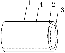
[0046] An embodiment of the present invention is a partial discharge source locating device for electrical equipment, which is an optical fiber differential pressure ultrasonic vector sensor. The optical fiber differential pressure ultrasonic vector sensor includes a sensor acoustic wave vibration sensing module and an optical system measurement module.

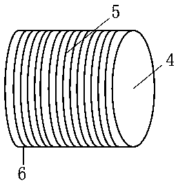
[0047] The acoustic wave vibration sensing module of the sensor in this embodiment includes a ceramic shell, an elastic cylinder and a vibrating diaphragm. The ceramic shell is a structure composed of six hollow cylinders, and the six hollow cylinders are six cylindrical sound pressure sensing elements 1; an elastic cylinder 4 is placed inside the hollow cylinder; the end of the cylindrical sound pressure sensing element is set There is a fixed elastic diaphragm 3, and an optical fib...


PUM


Abstract

The invention relates to a localization device and a localization method for electrical equipment partial discharge source. The device comprises six cylindrical sound pressure sensing primitives (1). The end part of each cylindrical sound pressure sensing primitive is provided with a fiber small hole (2). The end part of each cylindrical sound pressure sensing primitive is fixed with an elastic membrane (3). The internal of each cylindrical sound pressure sensing primitive is a coaxial hollow circular column, and each cylindrical sound pressure sensing primitive is internally provided with an elastic column (4) fixed on the bottom. Each elastic column is coiled with a fiber. The tail end of the fiber is plated with an aluminium membrane of high reflectivity. A laser emitted by a laser diode is input into an optical coupler via an optical isolator. Reflected interference light enters a photoelectric probe. The device adopts the differential structure, and thus isotropic noise in electrical equipment is offset in principle, thereby improving the signal to noise ratio. The invention adopts a method of locating the partial discharge source with the direction finding line minimum inscribed circle center principle. The invention can respond to supersonic signals of low energy, and has advantages of high sensitivity, large dynamic scope, anti-electromagnetic interference and high reliability.

Description

technical field [0001] The invention relates to a positioning device and a positioning method for partial discharge sources of electrical equipment, belonging to the technical field of electrical equipment detection. Background technique [0002] Oil is used as the insulating medium in many electrical equipment, which has the advantage of improving the insulation strength of the electrical equipment, cooling the electrical equipment through which a large current flows, and extinguishing the arc when an arc is generated inside the equipment. However, during the long-term operation of electrical equipment, due to problems such as insulation aging, overvoltage, or uneven structure of the insulation layer of electrical equipment, it is easy to cause local insulation performance to decline, and various types of discharges will occur first in these parts with weakened insulation, resulting in Further damage to the insulation causes various short-circuit faults to occur inside the ...

Claims


Application Information

Patent Timeline
Patent Type & Authority Patents(China)
IPC IPC(8): G01R31/12
CPCG01R31/1209
Inventor 宁涛谢庆王涛喻集文刘帆郭铁郑宜超李惟徐洁程述一
Owner ELECTRIC POWER RES INST STATE GRID JIANGXI ELECTRIC POWER CO
Learn More