Low NOx pulverized coal combustion system and method

A pulverized coal combustion and burner technology, which is applied in the combustion method, uses a variety of fuel combustion, combustion types, etc., can solve the problems of high NOx concentration in flue gas and cannot meet environmental requirements, achieves high-efficiency NOx emission reduction, and improves effective Residence time, the effect of NOx reduction

Inactive Publication Date: 2016-11-16
JIANGSU SUNPOWER TECH
View PDF4 Cites 5 Cited by
  • Summary
  • Abstract
  • Description
  • Claims
  • Application Information

AI Technical Summary

Problems solved by technology

[0004] The purpose of the present invention is to design a low-NOx pulverized coal combustion system that can greatly reduce the NOx emission concentration in view of the problem that the

Method used


Image

  • Low NOx pulverized coal combustion system and method
  • Low NOx pulverized coal combustion system and method
  • Low NOx pulverized coal combustion system and method

Examples


Embodiment 1

[0033] Such as Figure 1-5 shown.

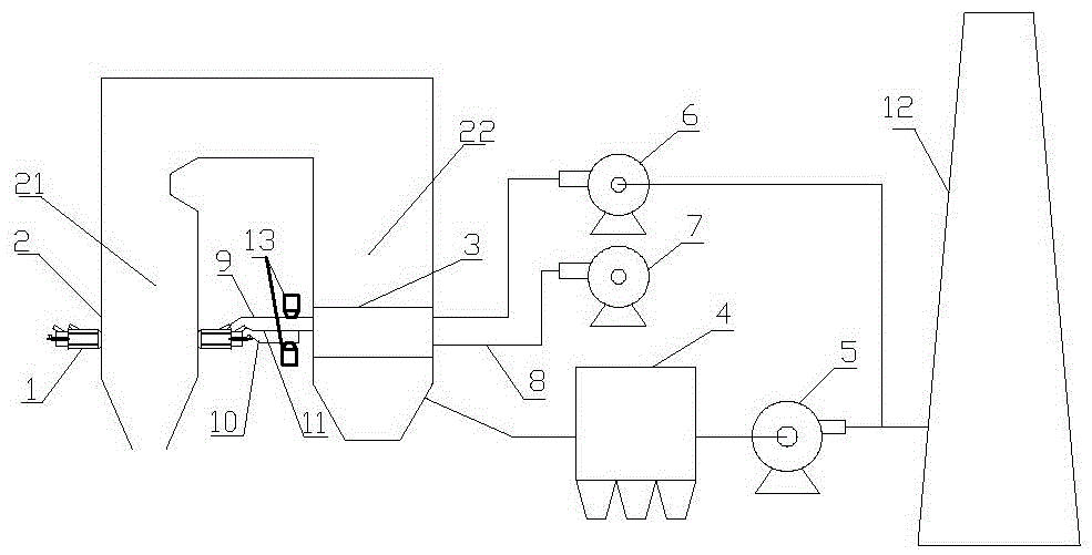
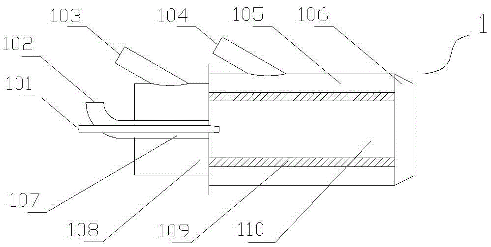
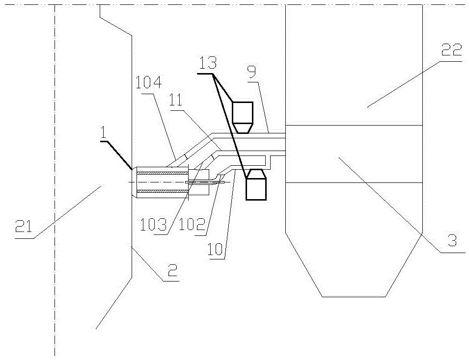
[0034] A low NOx pulverized coal combustion system, which includes a burner 1 (such as figure 2 ), powder milling and powder feeding system 13 (same as the existing technology, can be purchased directly from the market), boiler body 2, air preheater 3, dust collector 4 (bag type dust collector can be used), main induced draft fan 5, smoke Air circulation fan 6, primary fan 7, primary air pipe 8, flue gas return pipe 9, inner primary air pipe 10, outer primary air pipe 11 and chimney 12, such as figure 1 ; The boiler body 2, the dust collector 4, the main induced draft fan 5, and the chimney 12 are connected successively; the boiler body 2 is composed of a furnace 21 and a convective heat exchange section 22, and the furnace 21 and the convective heat exchange section 22 are arranged in parallel. They are connected through a horizontal channel. The furnace 21 is divided into a strong reduction zone, a reduction main combustion zone and a ...

Embodiment 2

[0041] Combustion method and process of the present invention are as follows:

[0042] A low NOx pulverized coal combustion method, the ultra-fine coal powder is sprayed into the primary combustion chamber through the inner primary air powder pipe, ignited and burned by the central igniter, and the outer primary air inlet pipe fills the primary combustion chamber with an appropriate amount of air to circulate the flue gas Carry pulverized coal through the flue gas ring, mix with the high-temperature combustion products of the primary combustion chamber at the air mixing ring, and spray them into the strong reduction zone of the furnace to participate in the combustion. The entire strong reduction zone is in high temperature, extremely low oxygen, and high inert gas Under the condition of high temperature and oxygen deficiency, pulverized coal reacts and carbonizes and pyrolyzes to form reducing gas, which reduces the original NOx in the primary combustion chamber and circulatin...


PUM


Abstract

Provided are a low NOx pulverized coal combustion system and method. The low NOx pulverized coal combustion system is characterized by comprising a burner (1), a powder making and supplying system (13), a boiler body (2), an air preheater (3), a dust remover (4), a main induced draft fan (5), a flue gas circulation fan (6), a primary fan (7), a primary air duct (8), a flue gas return tube (9), an inner primary air duct (10), an outer primary air duct (11) and a chimney (12); and the boiler body (2), the dust remover (4), the main induced draft fan (5) and the chimney (12) are sequentially connected. On the premise of improving the combustion stability and efficiency, a strong reducing area of combustion in a boiler is created effectively, the effective staying time of flue gas in the reducing area is prolonged, a certain turbulence degree of pulverized coal exists in a boiler hearth when in an extremely low excess air coefficient, the burn-off rate of combustion products in the boiler is improved, and NOx generated in the combustion process is restrained and reduced; and meanwhile, part of emitted flue gas is circulated, NOx carried in the flue gas is further reduced, and low NOx flue gas emission of the pulverized coal combustion system with high-efficiency combustion is achieved.

Description

technical field [0001] The invention relates to a pulverized coal combustion technology, in particular to a pulverized coal combustion technology suitable for a pulverized coal boiler, in particular to a pulverized coal combustion system and method with low NOx. Background technique [0002] At present, most of the existing industrial boilers in my country are coal-fired boilers. Since coal will produce a large amount of NOx during the combustion process, facing increasingly severe environmental problems, especially the impact of haze weather, the country's NOx emission requirements are increasingly strict. The Ministry of Environmental Protection's latest "Boiler Air Pollutant Emission Standards" stipulates that the NOx emission of newly built coal-fired industrial boilers is less than 300mg / m 3 , Boiler emissions in key areas are less than 200mg / m 3 . [0003] In order to make the NOx concentration of the boiler flue gas meet the national emission standards, it is necess...

Claims


Application Information

Patent Timeline
IPC IPC(8): F23C5/24F23C7/02F23C9/06F23L9/00F23L15/00F23J15/02
CPCF23C5/24F23C7/02F23C9/06F23C2202/20F23J15/02F23J2215/10F23L9/00F23L15/00Y02E20/34
Inventor 郭宏新袁琦何松刘丰张贤福赵志红
Owner JIANGSU SUNPOWER TECH
Why Eureka
Try Eureka