A dual frequency branch line coupler
A branch line and coupler technology, applied in the field of radio frequency and microwave, can solve the problems that the coupler is difficult to miniaturize, the frequency ratio adjustment range is wide, and cannot be realized in engineering, and achieves a large frequency ratio adjustment range, broad application prospects, and easy The effect of processing
- Summary
- Abstract
- Description
- Claims
- Application Information
AI Technical Summary
Problems solved by technology
Method used
Image

Examples
Embodiment 1
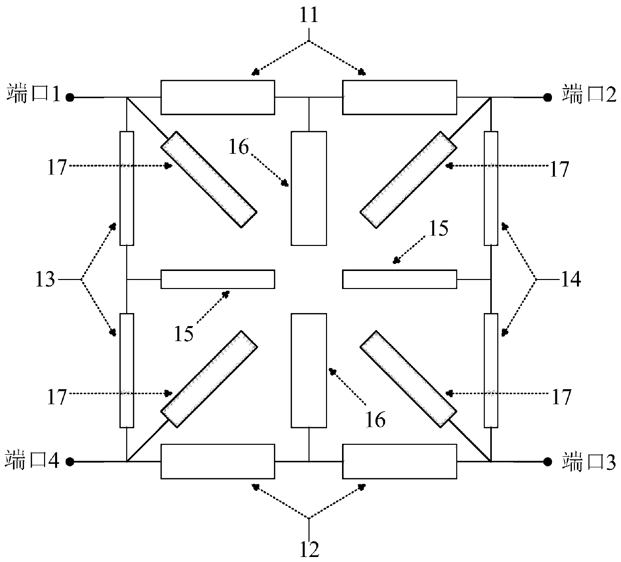
[0041] The topological structure diagram of the dual-frequency branch line coupler at 1GHz and 8GHz based on the central operating frequency realized by the present invention is as follows figure 1 As shown, the amplitude unbalance between the direct port 2 and the coupled port 3 is ±0.5dB; the phase difference between the two outputs of the coupled port 3 and the direct port 2 ∠31-∠21 is 90°±2.5° at 1GHz, and 90°±2.5° at 8GHz -90°±2.5°; port return loss greater than 15dB; isolation between through port 2 and coupled port 3 greater than 15dB. The specific design parameters are: the characteristic impedance of the two pairs of series microstrip lines corresponding to the first pair of transmission lines 11 and the second pair of transmission lines 12 is 73Ω, the characteristic impedance of the two pairs of series microstrip lines corresponding to the third pair of transmission lines 13 and the fourth pair of transmission lines 14 The characteristic impedance is 103Ω, the charac...
Embodiment 2
[0043] Based on the dual-frequency branch line coupler with a central operating frequency of 2.4GHz and 5.2GHz realized by the present invention, the unbalance degree of insertion loss between the through port and the coupled port is 0.5dB; the phase difference between the two outputs of the coupled port and the through port It is 90°±2.5° at 2.4GHz, and -90°±2.5° at 5.2GHz; port return loss is greater than 15dB; the isolation between input port and isolation port is greater than 15dB. In this embodiment, a microstrip transmission line is used, the relative permittivity of the dielectric substrate is 2.65, and the thickness of the dielectric plate is 1mm. Its topology is as follows Figure 5 As shown, the specific parameters of each part are as follows:
[0044] S1 is the input and output port transmission line with a characteristic impedance of 50 ohms, the corresponding microstrip line width is 2.71mm, and the length is 4mm;
[0045] S2 is a transmission line with a charact...
PUM
 Abstract
Description
Claims
Application Information
 - R&D
- Intellectual Property
- Life Sciences
- Materials
- Tech Scout
- Unparalleled Data Quality
- Higher Quality Content
- 60% Fewer Hallucinations
Browse by: Latest US Patents, China's latest patents, Technical Efficacy Thesaurus, Application Domain, Technology Topic, Popular Technical Reports.
© 2025 PatSnap. All rights reserved.Legal|Privacy policy|Modern Slavery Act Transparency Statement|Sitemap|About US| Contact US: help@patsnap.com