Vascular stent

A vascular stent and stent rod technology, used in the field of vascular stents, can solve the problems of affecting clinical effects, flexibility affecting stents through bending blood vessels, straightening blood vessels, etc., to achieve enhanced flexibility and expansion performance, good clinical treatment effect, high Effect of radial support force

Active Publication Date: 2016-11-23
MICROPORT NEUROTECH SHANGHAI
View PDF7 Cites 10 Cited by
  • Summary
  • Abstract
  • Description
  • Claims
  • Application Information

AI Technical Summary

Problems solved by technology

Among them, nickel-titanium alloy is preferred for self-expanding stent materials due to its high strength, fatigue resistance, corrosion resistance, wear resistance, good shape memory effect and good biocompatibility, although self-expanding stents have Such advantages, but the structural design of the stent will directly affect the performance of the stent, such as flexibility and expansion ability
Although the stent can be pressed and held on the delivery device, the flexibility of the stent will affect the bending ability of the stent in the delivery catheter. Poor flexibility will straighten the blood vessel, or it will be difficult to reach the lesion; even if it can reach the lesion smoothly , if the stent cannot be opened smoothly, it will affect the efficiency of the operation or lead to the failure of the operation process, and if it cannot be fully opened, it will also affect the postoperative clinical effect
Most of the current self-expanding stents choose the structural design of the V-shaped wave reinforcement ring 6, such as figure 1 As shown, although this structure has good supporting force, the lack of flexibility affects the ability of the stent to pass through the curved blood vessel; in addition, the existing vascular stents often limit the ability of the stent to expand circumferentially, and the stent may not be opened. situation

Method used


Image

  • Vascular stent
  • Vascular stent
  • Vascular stent

Examples


Embodiment Construction

[0034] The present invention will be further described below in conjunction with the accompanying drawings and embodiments.

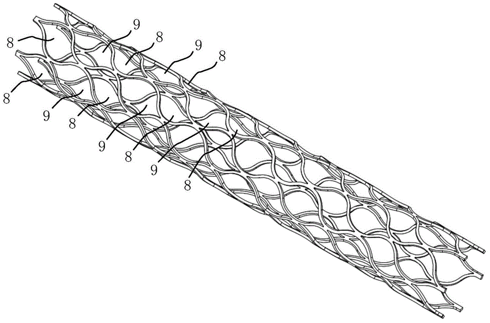
[0035] image 3 It is a schematic diagram of the structure of the vascular stent in the embodiment of the present invention.

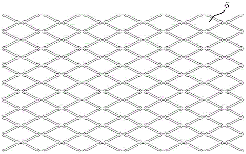
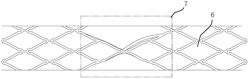
[0036] For self-expanding stents, different structures and size designs will affect the compliance performance of the stent, and the structural design will also affect the expansion performance. See image 3 , the vascular stent provided by the present invention is composed of a plurality of unit rings arranged to form a tubular structure, the unit rings include a first unit ring 8 and a second unit ring 9, and the area enclosed by the first unit ring 8 is smaller than that of the second unit ring 9 coverage area, the first unit rings 8 and the second unit rings 9 are alternately arranged at intervals. The first unit ring 8 is arranged along the circumferential direction of the blood vessel stent to form a first unit ring, an...


PUM


Abstract

The invention discloses a vascular stent. Multiple unit rings are arranged to form a tubular structure, wherein the unit rings comprise the first unit rings and the second unit rings, the area formed by each first unit ring in an enclosing mode is smaller than that formed by each second unit ring in an enclosing mode, and the first unit rings and the second unit rings are arranged in a spaced and staggered mode. The first unit rings and the second unit rings have a central point symmetry structure, the vascular stent presents a tubular stent after being unfolded, and included angles are axially formed between the first unit rings and the second unit rings and the tubular stent. According to the vascular stent, the net-shaped structure is formed by arranging the two kinds of unit rings with the different sizes in the spaced mode, high radial support force is achieved, and therefore the flexibility and the expansion property of the stent can be greatly enhanced; in addition, by designing the inclination angles of the two kinds of unit rings, the flexibility and the expansion property of the stent are further enhanced, and it is guaranteed that the force borne by the stent is effectively transmitted in the direction of a stent rod.

Description

technical field [0001] The invention relates to the field of vascular interventional medicine, in particular to a vascular stent. Background technique [0002] At present, arterial stenosis is a disease with high mortality and high disability rate. Endovascular interventional treatment of vascular stents has gradually become the main treatment method for this vascular disease. The principle is that the implanted stent usually reaches the lesion site through the delivery system. The arterial narrowing is then treated by dilating and rebuilding the blood vessel. This method has the following advantages: less trauma, less complications, high safety, less pain for patients, easy to accept, short hospital stay, and can be tolerated by elderly patients with severe illness. [0003] Among the performance indicators of the stent, the compliance and expansion properties of the stent play a crucial role in the clinical effect both during and after the operation. The compliance perfo...

Claims


Application Information

Patent Timeline
Patent Type & Authority Applications(China)
IPC IPC(8): A61F2/91
Inventor 倪尊张郭远益陈冰金巧蓉谢志永
Owner MICROPORT NEUROTECH SHANGHAI
Why Eureka
Try Eureka