
Steel plate surface polishing device for hardware machining

A surface polishing and steel plate technology, applied in surface polishing machine tools, grinding/polishing safety devices, heating devices, etc., can solve the problems of immature and professional polishing technology, affecting the health of operators, and expensive polishing machines. Achieve the effect of high cost performance, low professional requirements and good welding performance

Active Publication Date: 2016-11-23
如皋市通城冲压机械制造有限公司
View PDF6 Cites 67 Cited by
  • Summary
  • Abstract
  • Description
  • Claims
  • Application Information

AI Technical Summary

Problems solved by technology

[0005] The present invention overcomes the fact that the current grinding and polishing of steel plates mainly relies on manpower, the polishing technology is immature and its professionalism is strong, while the polishing machine is expensive, heavy, complicated to operate, low in safety factor, and the environment during working is harmful to the operation. The shortcoming that the health of personnel is affected, the technical problem to be solved in the present invention is to provide a kind of operation technology that does not require manual labor, does not require high professionalism, simple operation, high cost performance, high safety factor, and the operating environment is harmful to the health of operators. Smaller steel plate surface polishing device for metal processing

Method used


Image

  • Steel plate surface polishing device for hardware machining
  • Steel plate surface polishing device for hardware machining
  • Steel plate surface polishing device for hardware machining

Examples


Embodiment 1

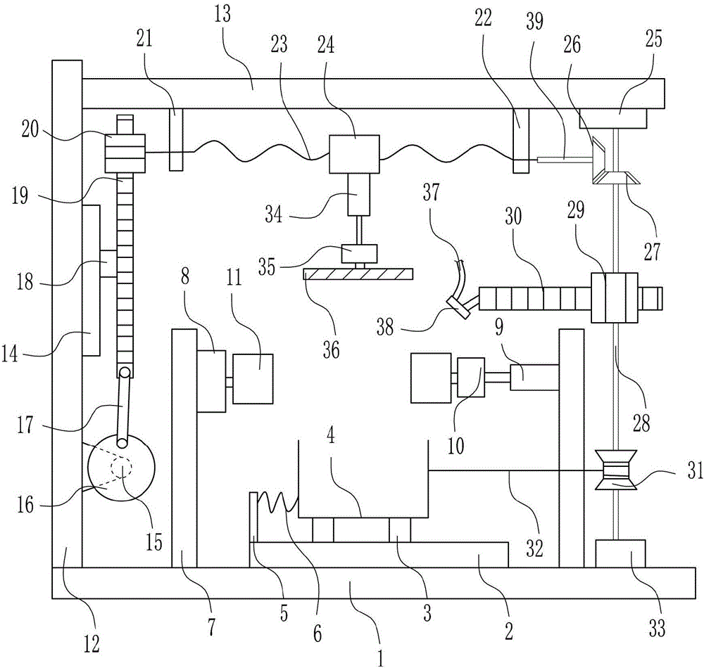
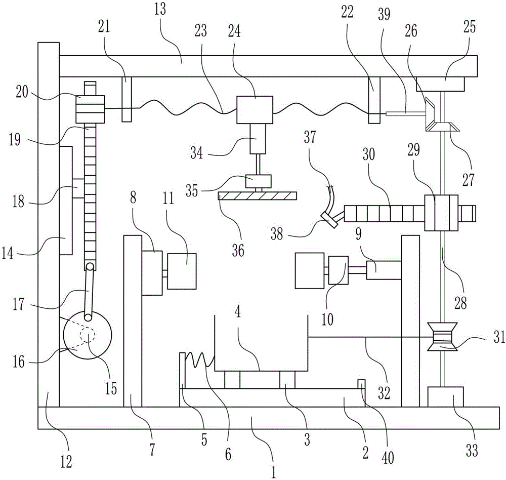
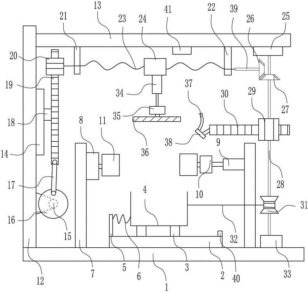
[0027] A steel plate surface polishing device for hardware processing, such as Figure 1-3 As shown, it includes a bottom plate 1, a first slide rail 2, a first sliding block 3, a collection box 4, a fixed stop 5, a spring 6, a support rod 7, a first bearing seat 8, a first cylinder 9, and a first motor 10. Thumb cylinder 11, left side plate 12, top plate 13, second slide rail 14, second motor 15, disc 16, connecting rod 17, second slider 18, first rack 19, first gear 20, Left bearing seat 21, right bearing seat 22, screw rod 23, nut 24, upper bearing seat 25, first bevel gear 26, second bevel gear 27, first shaft 28, second gear 29, second rack 30, The winding wheel 31, the pulling wire 32, the lower bearing seat 33, the second cylinder 34, the third motor 35, the grinding disc 36, the water inlet pipe 37, the spray head 38 and the second rotating shaft 39, the bottom plate 1 has a first slide rail 2 in the middle, The first slide rail 2 is symmetrically slidably connected to...


PUM


Abstract

The invention relates to a steel plate surface polishing device, in particular to a steel plate surface polishing device for hardware machining. The steel plate surface polishing device for hardware machining aims to achieve the technical purposes that manual labor is not needed, the requirement for professional operation skills is not high, operation is easy, the price-performance ratio is high, the safety coefficient is high, and harm of the operation environment to health of operators is small. In order to achieve the technical purposes, the steel plate surface polishing device for hardware machining comprises a bottom plate, a first sliding rail, a first sliding block, a collection tank, a fixing stop block, a spring, a supporting rod, a first bearing pedestal, a first air cylinder, a disc and the like, wherein the first sliding rail is arranged in the middle of the top of the bottom plate. Through ingenious cooperation of the components, the effects that manual labor is not needed, the requirement for professional operation skills is not high, operation is easy, the price-performance ratio is high, the safety coefficient is high, and harm of the operation environment to health of the operators is small are achieved.

Description

Technical field [0001] The invention relates to a steel plate surface polishing device, in particular to a steel plate surface polishing device for hardware processing. Background technique [0002] The steel plate is a flat-shaped steel that is poured with molten steel and pressed after cooling. The steel plate is flat and rectangular, and can be directly rolled or cut from a wide steel strip. Steel plates are divided into thicknesses, thin steel plates <4 mm (the thinnest 0.2 mm), thick steel plates 4-60 mm, and extra-thick steel plates 60-115 mm. Steel plates are divided into hot rolling and cold rolling according to rolling. The width of the thin plate is 500-1500 mm; the width of the thick is 600-3000 mm. Thin plates are classified according to steel types, including ordinary steel, high-quality steel, alloy steel, spring steel, stainless steel, tool steel, heat-resistant steel, bearing steel, silicon steel and industrial pure iron thin plates. According to professiona...

Claims


Application Information

Patent Timeline
IPC IPC(8): B24B29/02B24B41/02B24B47/14B24B55/00B24B41/06B24B55/06F26B23/04
CPCB24B29/02B24B41/02B24B41/06B24B47/14B24B55/00B24B55/06F26B23/04
Inventor 朱连成
Owner 如皋市通城冲压机械制造有限公司
Learn More