A sncr-scr combined flue gas denitrification system

A flue gas and denitrification technology, which is applied in the field of flue gas denitrification system, can solve the problems affecting the denitrification efficiency of SNCR and SCR, large fluctuations in boiler flue gas temperature, and shortened catalyst life, so as to facilitate transformation, reduce energy consumption, and reduce emissions Effect

Active Publication Date: 2019-01-08
JIAXING NEW JIES THERMAL POWER
View PDF9 Cites 0 Cited by
  • Summary
  • Abstract
  • Description
  • Claims
  • Application Information

AI Technical Summary

Problems solved by technology

This characteristic of the heating boiler leads to large fluctuations in the boiler smoke temperature, and the size of the boiler smoke temperature directly affects the denitrification efficiency of SNCR and SCR
When the furnace is operating at a high load, the flue gas at the furnace outlet will be higher than the reaction temperature range (850°C~1100°C) for effective denitrification by SNCR. improvement
At the same time, when the high-temperature flue gas passes through the SCR reaction device, its temperature may still be higher than the optimal reaction temperature of the SCR device, which will promote the sintering of the catalyst surface and reduce the catalyst life.

Method used


Image

  • A sncr-scr combined flue gas denitrification system

Examples


Embodiment Construction

[0025] It should be understood that the above-mentioned drawings are not true to scale, but merely schematic diagrams illustrating various preferred features illustrating the basic principles of the invention. The design features disclosed in the present invention, such as size, orientation, orientation and shape are determined according to the specific application and use environment. In addition, in the following description, terms such as "front", "rear", "before", "rear", "front end", "rear end" and other descriptions are defined relative to the flow direction of smoke.

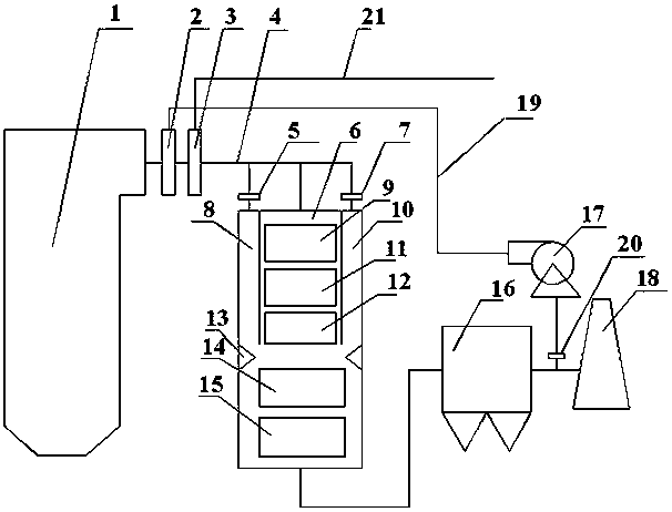
[0026] Combine below figure 1 Specific examples of the present invention will be described in detail.

[0027] A boiler in a thermal power plant is used to burn coal, and the boiler may be, for example, a fluidized bed boiler. The flue gas in the coal combustion enters the horizontal flue 4 from the outlet of the furnace 1 . In the horizontal flue 4, the ammonia injection grid 3 is vertically arranged,...


PUM


Abstract

The invention relates to an SNCR-SCR combined flue gas denitrification system, which comprises a horizontal flue channel, a main flue channel connected to the horizontal flue channel, and a chimney connected to the outlet of the main flue channel, wherein an ammonia spraying grid is arranged in the horizontal flue channel, and a SCR reaction device is arranged in the main flue channel. The SNCR-SCR combined flue gas denitrification system is characterized in that the system further comprises a flue gas returning device arranged between the main flue channel and the chimney and used for selectively returning the flue gas outflowing from the main flue channel to the horizontal flue channel. The SNCR-SCR combined flue gas denitrification system of the present invention has effects of flue gas flow direction adjusting, denitrification efficiency improving, and nitrogen oxide emission reducing.

Description

technical field [0001] The invention relates to a flue gas denitration system, in particular to a selective non-catalytic reduction (SNCR) and selective catalytic reduction (SCR) combined flue gas denitrification system. Background technique [0002] At present, the tail gas denitrification technologies of coal-fired boilers in thermal power plants include SNCR technology and SCR technology. [0003] SNCR denitrification technology is to spray reducing agents such as ammonia gas, ammonia water or urea into boilers or pipelines, and nitrogen oxides (NO x ) for a selective reaction without a catalyst, so a reducing agent must be added in the high temperature zone. Generally, it works in the temperature range of 850-1100°C. At this temperature, the reducing agent rapidly thermally decomposes into ammonia gas, which reacts with NO in the flue gas. x The reaction produces nitrogen and water vapor. When the temperature is lower than 800°C, the reaction rate of ammonia decreases...

Claims


Application Information

Patent Timeline
Patent Type & Authority Patents(China)
IPC IPC(8): B01D53/75B01D53/56
Inventor 王怡弘计荣林俞保云胡宁庄建发孟志浩
Owner JIAXING NEW JIES THERMAL POWER
Why Eureka
Try Eureka