
A method and device for laser shot peening of aircraft wings

A technology of laser peening forming and laser peening, which is applied in the field of mechanical engineering, can solve the problems of unsuitable large-size parts, etc., and achieve the effects of improving precision, simple device, and easy control method

Active Publication Date: 2018-01-23
GUANGDONG UNIV OF TECH
View PDF6 Cites 0 Cited by
  • Summary
  • Abstract
  • Description
  • Claims
  • Application Information

AI Technical Summary

Problems solved by technology

At the same time, it provides a laser shot peening forming device and control method for aircraft wings, which solves the problem that the existing device is not suitable for large-sized parts

Method used


Image

  • A method and device for laser shot peening of aircraft wings
  • A method and device for laser shot peening of aircraft wings
  • A method and device for laser shot peening of aircraft wings

Examples


Embodiment 1

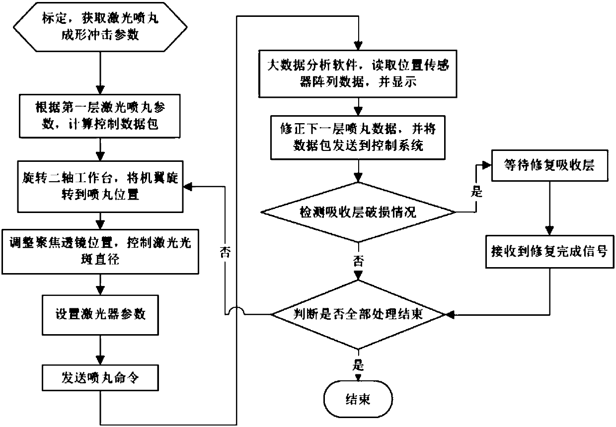
[0045] In this embodiment, the invention provides a method for impact forming of an aircraft wing, the flow chart of which is as follows figure 1 shown, including the following steps:

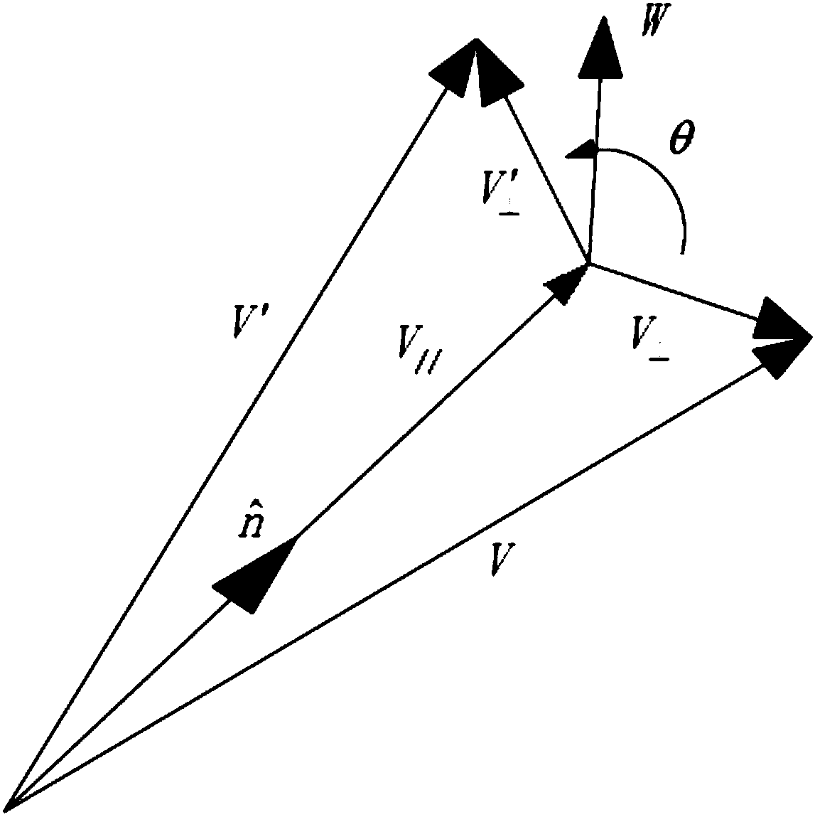
[0046]Step 1: Calibrate the aircraft wing to obtain the layered impact parameters of laser peening. First, the big data software reads the 3D model data of the aircraft wing parts and the blank, and interpolates the machining allowance between the aircraft wing parts and the blank according to the elastic-plastic properties of the material to obtain the laser shot peening layered data; Secondly, the big data analysis system plans a variety of laser peening trajectories and processing parameters on each layer, and generates simulation files that can be recognized by finite element analysis software, such as the INP file format that can be recognized by Abaqus software. Call the finite element simulation software to calculate and analyze the simulation file; read the calculation results of the f...

Embodiment 2

[0079] The present embodiment provides a kind of aircraft wing impact forming method, it is characterized in that, comprises the following steps:

[0080] Step 1: Calibrate the aircraft wing to obtain the layered impact parameters of laser peening;

[0081] Step 2: The big data analysis system calculates the laser peening control data packet according to the first-layer layered impact parameters, and sends the data packet to the control system;

[0082] Step 3: The control system controls the two-axis workbench to rotate the aircraft wing to the impact position according to the information in the data packet;

[0083] Step 4: The control system moves the lens assembly to the peening position according to the information in the data packet, and adjusts the focus lens position of the lens assembly, and adjusts the laser spot diameter;

[0084] Step 5: the control system sets the first layer of laser peening parameters according to the information in the data packet;

[0085] S...


PUM


Abstract

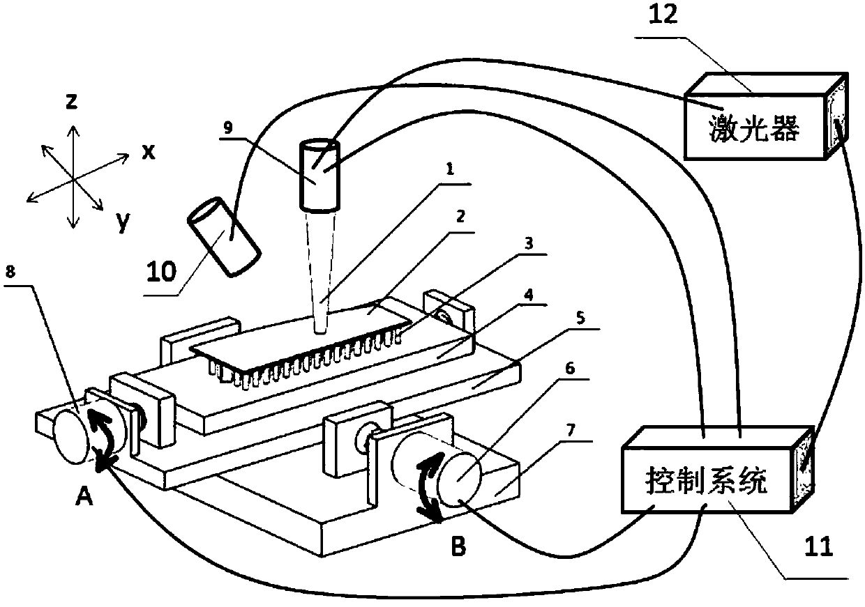
The invention relates to a method and device for laser shot-blasting forming of an aircraft wing. The device for laser shot-blasting forming of the aircraft wing is composed of a two-axis rotating workbench, a laser device, a lens assembly, a control device, a big data analysis system and the like. The control device plans position information of laser shock according to information of the big data analysis system and controls the two-axis rotating workbench to rotate according to the position information, so that the wing is rotated to the shock position, and the lens assembly is controlled to move to the shock position at the same time. The lens assembly measures the distance between the shock position and a lens and moves the focusing lens to focus lasers to the shock position, and the required spot diameter is obtained. After the lens assembly is positioned, a signal is emitted to a control system, the control system controls the laser device to emit lasers according to planned laser shock parameters, shock waves generated by the lasers are used for making a workpiece deform, and thus forming is achieved.

Description

technical field [0001] The invention belongs to the technical field of mechanical engineering, in particular to an aircraft wing impact forming method and a control device. Background technique [0002] Laser shot peening is to irradiate the surface of the material with short-pulse high-power laser, the material is vaporized and a high-pressure shock wave is generated on the surface of the plate. When the shock wave intensity is greater than the dynamic yield strength of the material, the plate will undergo plastic deformation, thereby causing the plate to Bi-directional bending deformation that is convex toward the sprayed surface. Laser shot peening has the advantages of no mold, simple process equipment, large processing flexibility, precise control of the laser pulse parameters can accurately control the shape of the shot peening, the forming curvature is larger than that of mechanical shot peening, and the compressive stress on the surface of the part can improve the fa...

Claims


Application Information

Patent Timeline
Patent Type & Authority Patents(China)
IPC IPC(8): B21D53/92B21D26/00
CPCB21D26/00B21D53/92
Inventor 张永康肖爱民王冠罗红平郭钟宁张永俊
Owner GUANGDONG UNIV OF TECH
Learn More