High-temperature crystal growth technology for polysilicon semi-molten ingot
A technology of polycrystalline silicon and crystal growth, which is applied in the direction of polycrystalline material growth, crystal growth, single crystal growth, etc., can solve the problem that it cannot be discharged in time, and some parts are directly solidified to form hard spots, affecting the quality and yield of ingot products, The problem of keeping the molten state at the top for less time achieves the effects of improving the quality of growing crystals, reducing the rate of cutting wire breakage, and increasing the degree of supercooling
- Summary
- Abstract
- Description
- Claims
- Application Information
AI Technical Summary
Problems solved by technology
Method used
Image
Examples
Embodiment 1
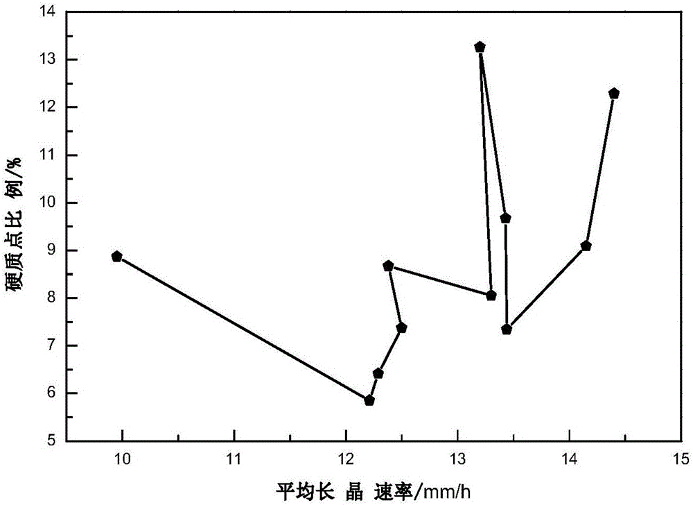
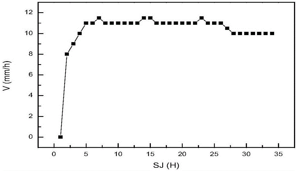
[0046] During the crystal growth process, the growth rate of the top segment and the bottom segment of the polysilicon ingot is 10mm / h, the growth rate of the middle segment of the polysilicon ingot is 10mm / h, the gas pressure is maintained at 400MPa, the top pipe and the bottom pipe Argon gas flow rate is 0.2L / min.
[0047] Step 1. Rapidly lower the temperature of the ingot casting furnace from 1550° C. to 1440° C. after 30 minutes, and keep it warm for 20 minutes; the lifting height of the heat insulation cage of the ingot casting furnace is 60 mm; adjust the power ratio of the top and side heaters to 0.8:0.2.
[0048] Step 2. Control the heating temperature of the ingot casting furnace at 1440°C and keep it warm for 60 minutes. When the temperature gradually drops to 1440°C, adjust the power ratio of the top heater and the side heater to 0.2:0.6 to ensure crystal growth During the process, there is sufficient temperature gradient between the top and the bottom, and at the ...
Embodiment 2
[0053] During the crystal growth process, the growth rate of the top segment and the bottom segment of the polysilicon ingot is 10mm / h, the growth rate of the middle segment of the polysilicon ingot is 11mm / h, the gas pressure is maintained at 500MPa, the top pipe and the bottom pipe Argon gas flow rate is 0.4L / min.
[0054] Step 1. Rapidly lower the temperature of the ingot casting furnace from 1552° C. to 1442° C. after 35 minutes, and keep it warm for 25 minutes; the lifting height of the heat insulation cage of the ingot casting furnace is 75 mm; adjust the power ratio of the top and side heaters to 0.8:0.2.
[0055] Step 2. Control the heating temperature of the ingot casting furnace at 1442°C and keep it warm for 80 minutes; when the temperature gradually drops to 1440°C, adjust the power ratio of the top heater and the side heater to 0.2:0.6 to ensure crystal growth During the process, there is sufficient temperature gradient between the top and bottom, and at the same...
Embodiment 3
[0060] During the crystal growth process, the growth rate of the top segment and the bottom segment of the polysilicon ingot is 11mm / h, the growth rate of the middle segment of the polysilicon ingot is 12mm / h, the gas pressure is maintained at 550MPa, the top pipe and the bottom pipe Argon gas flow rate is 0.6L / min.
[0061] Step 1. Rapidly lower the temperature of the ingot casting furnace from 1554° C. to 1444° C. in 38 minutes, and keep it warm for 30 minutes; the lifting height of the heat insulation cage of the ingot casting furnace is 85 mm; adjust the power ratio of the top and side heaters to 0.8:0.2.
[0062] Step 2. Control the heating temperature of the ingot casting furnace at 1444°C and keep it warm for 100 minutes; when the temperature gradually drops to 1440°C, adjust the power ratio of the top heater and the side heater to 0.2:0.6 to ensure crystal growth During the process, there is sufficient temperature gradient between the top and bottom, and at the same t...
PUM
 Abstract
Description
Claims
Application Information
 - R&D
- Intellectual Property
- Life Sciences
- Materials
- Tech Scout
- Unparalleled Data Quality
- Higher Quality Content
- 60% Fewer Hallucinations
Browse by: Latest US Patents, China's latest patents, Technical Efficacy Thesaurus, Application Domain, Technology Topic, Popular Technical Reports.
© 2025 PatSnap. All rights reserved.Legal|Privacy policy|Modern Slavery Act Transparency Statement|Sitemap|About US| Contact US: help@patsnap.com


