
Film system design of reducing aberration generated because of observation angle changes and manufacturing method thereof

A technology of viewing angle and film system design, applied to optical components, optics, instruments, etc., can solve problems such as aggravating color uniformity and inevitable changes in interference results

Active Publication Date: 2016-12-07
CHINA BUILDING MATERIALS ACAD
View PDF3 Cites 4 Cited by
  • Summary
  • Abstract
  • Description
  • Claims
  • Application Information

AI Technical Summary

Problems solved by technology

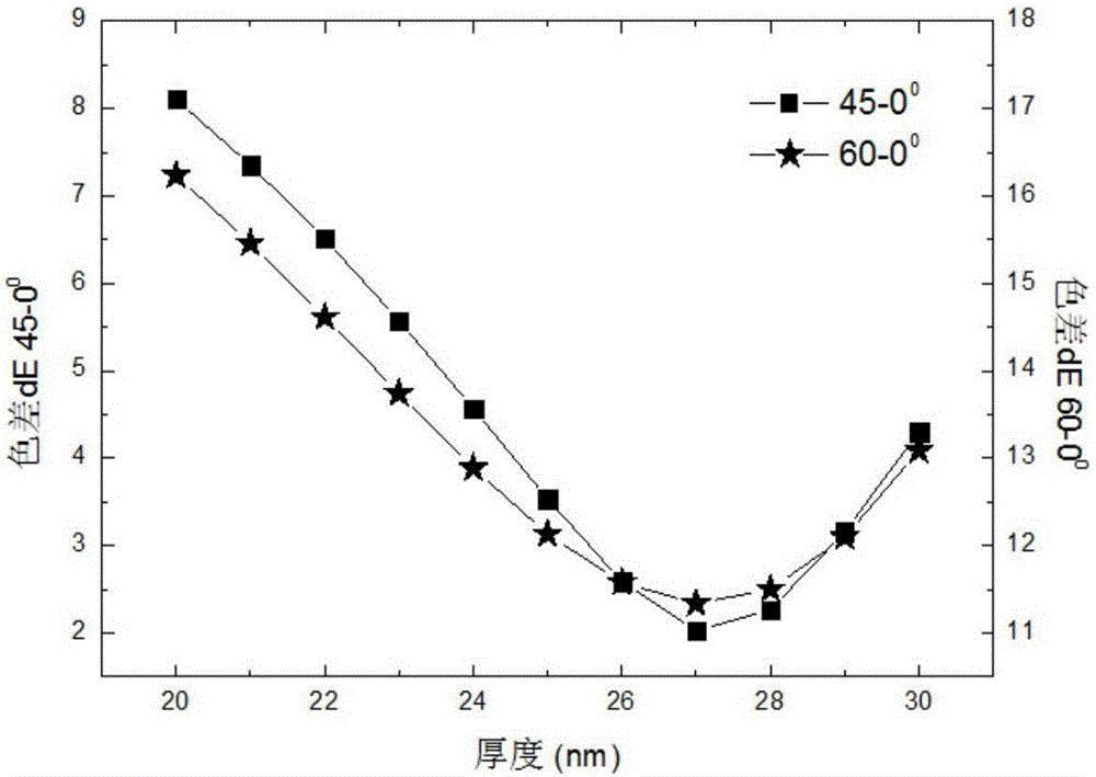
[0003] Since the interference result of each film layer is determined by the optical thickness of the film layer, compared with the observation angle of 0 degrees, the optical thickness of the film layer under other observation angle conditions increases, so the interference result will inevitably change. The color obtained by the observer when the angle changes is different. In addition, for large-area coated products, the thickness of each film layer fluctuates in a large area due to the limitation of process conditions. When the viewing angle becomes larger, the fluctuation of film thickness is also enlarged. Therefore color uniformity issues are exacerbated when viewed at large angles

Method used


Image

  • Film system design of reducing aberration generated because of observation angle changes and manufacturing method thereof
  • Film system design of reducing aberration generated because of observation angle changes and manufacturing method thereof
  • Film system design of reducing aberration generated because of observation angle changes and manufacturing method thereof

Examples


Embodiment 1

[0053] An embodiment of the present invention proposes a film system design and preparation method to reduce the chromatic aberration caused by the change of the observation angle, taking magnetron sputtering plating large-area double silver offline low-emissivity coated glass as an example. Table 1 shows the target configuration of the production line Position, target configuration, and the film sequence determined, the substrate is architectural float glass with a thickness of 5.86mm; when using magnetron sputtering to coat the film of low-emissivity coated glass, Si:Al, Zn:Al are used , Zn:Sn alloy target reactive sputtering to generate the corresponding film SiN x , ZnO x , ZnSnO x , Use metal target sputtering to deposit the corresponding film layer Ag, NiCr.

[0054] Table 1 Production line double-silver configuration target target material and corresponding film sequence

[0055] order

1

2

3

4

5

6

7

8

9

10

Target

Si:Al

Zn:Al

Ag

NiCr

Zn:Sn

Zn:Al

Ag

NiCr

Zn:Sn

Si:Al

Fi...

Embodiment 2

[0075] An embodiment of the present invention proposes a film system design and preparation method for reducing the chromatic aberration caused by the change of the observation angle. Taking magnetron sputtering plating large-area single silver offline low-emissivity coated glass as an example, the present invention proposes to reduce the observation The film system design method for chromatic aberration caused by the angle change is designed to optimize the film system performance. Table 7 shows the target position, target configuration and film structure of a blue-gray single silver coated glass production line with a transmittance greater than 50%. Initial design. Table 8 shows the performance results of the initial design single silver film system.

[0076] Table 7 Production line single silver configuration target position, target material and initial design of film system (thickness: nm)

[0077]

[0078] Table 8 Initial design single silver film performance

[0079]

[0080]...


PUM


Abstract

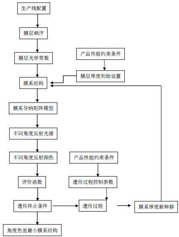
The invention discloses a film system design of reducing an aberration generated because of observation angle changes and a manufacturing method thereof. The design method comprises the following steps of 1) according to a product performance integration requirement and a production condition, establishing a film system thickness reasonable design scope; 2) according to product performance, carrying out film layer initial setting, forming an initial value and establishing an admittance matrix optical model; and 3) using a genetic algorithm to analyze glass surface reflection spectrums and colors of the film system under different observation angle conditions and acquiring a film system structure which has a minimum aberration when the angle changes. In the invention, repeated product debugging and performance test processes are avoided; and a design result can be rapidly acquired, product performance is optimized, product design exploitation cost is reduced and a product exploitation period is shortened.

Description

Technical field [0001] The invention relates to a film system design and preparation method, in particular to a film system design and preparation method that reduces the chromatic aberration caused by the change of the observation angle. Background technique [0002] Improving the optical performance of the material is one of the main purposes of coating the surface of the material. Offline low-radiation Low-E coated glass is to use magnetron sputtering coating method to coat multiple layers of film on the glass surface, so that the architectural float glass has low radiation , Shading and meeting the color design requirements of building appearance, and its optical performance is evaluated by indicators such as emissivity, visible light transmittance, sunlight transmittance, color, etc. These optical properties are the result of the interference of each layer of the film system, which is directly It is embodied as the transmission and reflection spectrum data of the product, an...

Claims


Application Information

Patent Timeline
Patent Type & Authority Applications(China)
IPC IPC(8): G02B27/00
CPCG02B27/0012G02B27/0025
Inventor 余刚汪洪
Owner CHINA BUILDING MATERIALS ACAD
Learn More