Amorphous alloy iron core permanent magnet brushless direct-current motor

A permanent magnet brushless DC and amorphous alloy technology, which is applied in the direction of electrical components, electromechanical devices, electric components, etc., can solve the problem that the energy efficiency ratio and power density of the motor need to be further improved, and the permanent magnet brushless DC motor cannot be used alone. Plug-in reliability discounts and other issues to achieve the effect of improving efficiency and power density, reducing iron loss, and overall optimization

Active Publication Date: 2016-12-07
彭希南
View PDF4 Cites 17 Cited by
  • Summary
  • Abstract
  • Description
  • Claims
  • Application Information

AI Technical Summary

Problems solved by technology

However, the current effective materials for permanent magnet brushless DC motors, such as electrical steel sheets and conductive materials, basically follow the traditional silicon steel sheets and enameled wires. There is room for improvement, the energy efficiency ratio and power density of the motor need to be further improved
On the other hand, in terms of installation and control mode, the permanent magnet brushless DC motor adopts the form of independent separation of the motor body and the controller, which makes the existing permanent magnet brushless DC motor inconvenient to use. The brushed DC motor cannot be used alone, it must cooperate with the controller to work normally, and there are many complicated control connections between the permanent magnet brushless DC motor and the controller, it is very troublesome to use and identify, and the connecting wires use connectors The reliability is also greatly reduced

Method used


Image

  • Amorphous alloy iron core permanent magnet brushless direct-current motor
  • Amorphous alloy iron core permanent magnet brushless direct-current motor
  • Amorphous alloy iron core permanent magnet brushless direct-current motor

Examples


Embodiment Construction

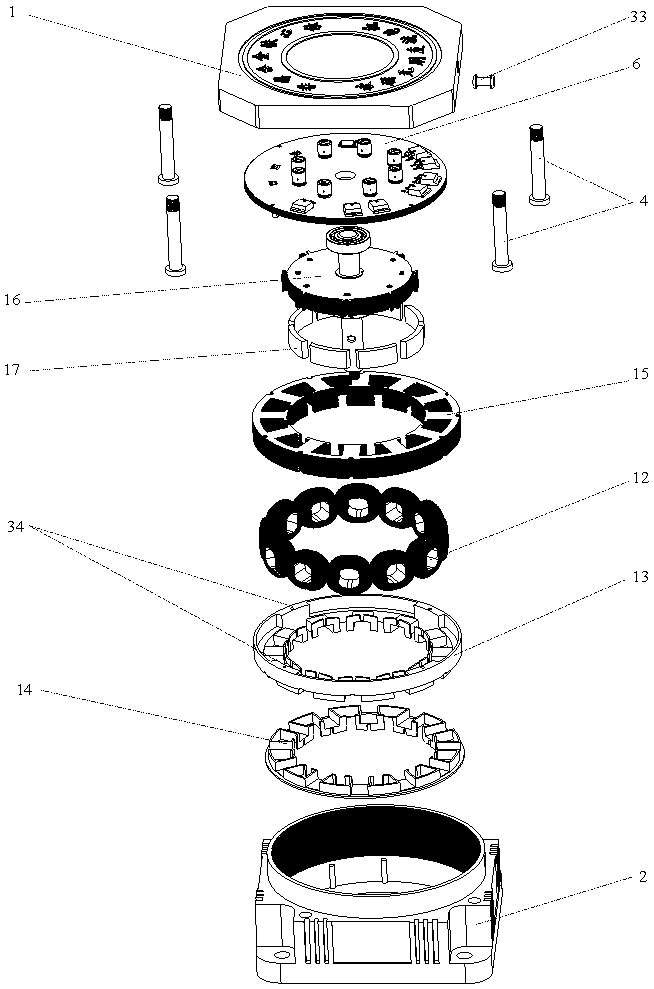
[0058] The invention as Figure 1 to Figure 10 shown.

[0059] Specific embodiments of the present invention will be described below in conjunction with the accompanying drawings.

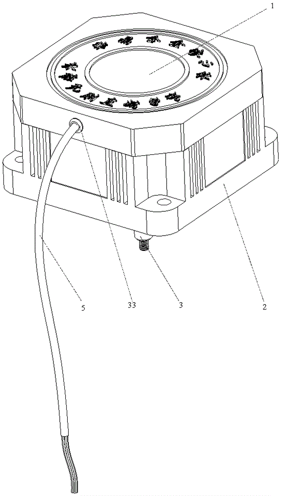
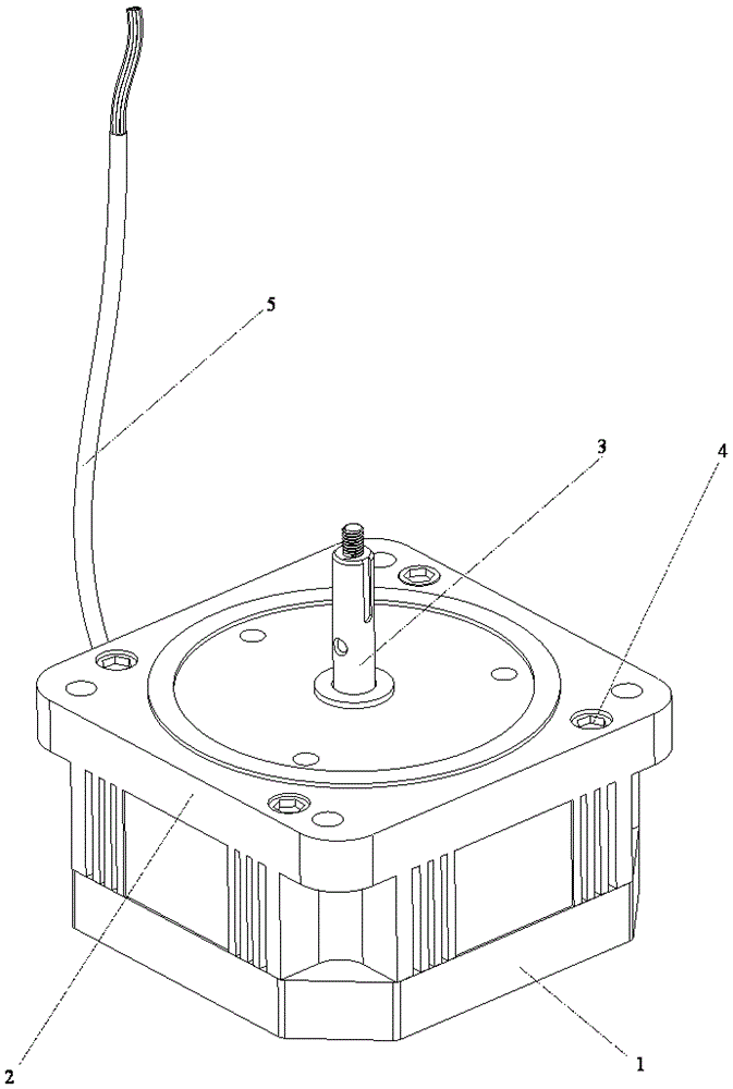
[0060] An amorphous alloy iron core permanent magnet brushless DC motor, which consists of a motor body and a controller. The motor body part includes a motor upper end cover 1, a motor lower end cover 2, a motor output shaft 3, a motor upper end cover 1 and a motor lower end Outlet hole 20 on the cover 2, cable retaining ring 33, shaft sleeve 39, upper frame 13, lower frame 14, stator coil 12, stator core body 15, rotor core body 16, NdFeB permanent magnet block 17, upper bearing 18. Lower bearing 19. Fixing screw 4. The controller part includes aluminum metal-based printed circuit board 6. Control cable 5. Dual-core single-chip microcomputer 8. Power VMOS tube 7. Hall element A for position sensing 9. Hall element B 10. Hall element C 11, the main points of which are: the permanent magnet brush...


PUM


Abstract

An amorphous alloy iron core permanent magnet brushless direct-current motor consists of the two portions including a motor body and a controller, wherein the motor body portion comprises a motor upper end cap, a motor lower end cap, a motor output shaft, a shaft sleeve, an upper framework, a lower framework, a stator coil, a stator iron core body, a rotor iron core body and neodymium iron boron permanent magnet block, and the controller portion comprises an aluminum metal based printing circuit board, a control cable, a double-core single chip microcomputer, a power VMOS tube and a Hall element. The amorphous alloy iron core permanent magnet brushless direct-current motor is characterized in that both the stator iron core body and the rotor iron core body are formed by superposing iron based amorphous alloy sheets, the stator iron core body is fixed through joint supporting of the upper framework and the lower framework, the stator coil is made by winding an anaerobic copper line, all of controller elements and circuits are integrated on the aluminum metal based printing circuit board, an outer thread is carved on the supporting aluminum metal cylinder of the aluminum metal based printing circuit board, the cylinder is screwed into the inner wall thread of the motor lower end cap during installation to form a motor body and controller mechanical-electrical integrated structure.

Description

technical field [0001] The permanent magnet brushless DC motor with an amorphous alloy iron core body involved in the present invention is a brushless DC motor with high power density and high efficiency, and is mainly used in aerospace, new energy electric vehicles, various high-end household appliances and industrial control drive field. Background technique [0002] Since 1978, when the original Sidmann Nessmann company launched the first square-wave brushless DC motor and its driver at the Hannover Trade Fair, permanent magnet brushless DC motors have made great progress in manufacturing and control technology. , and are widely used in DC inverter air conditioners, household appliances, electric vehicles, electric motorcycles, hybrid vehicles, electric yachts, aerospace and various industrial speed control motor control fields. However, the current effective materials for permanent magnet brushless DC motors, such as electrical steel sheets and conductive materials, b...

Claims


Application Information

Patent Timeline
Patent Type & Authority Applications(China)
IPC IPC(8): H02K11/30H02K29/08H02K3/02H02K5/04
CPCH02K3/02H02K5/04H02K29/08
Inventor 彭希南
Owner 彭希南
Why Eureka
Try Eureka