Method for removing ceramic layers of thermal barrier coating

A technology of thermal barrier coating and ceramic layer, applied in the direction of liquid cleaning method, chemical instrument and method, cleaning method and utensils, etc., can solve the problem of metal bottom layer thinning, etc., and achieve easy recoating and reasonable angle design , Improve the removal effect

Inactive Publication Date: 2017-01-04
AECC AVIATION POWER CO LTD
View PDF7 Cites 7 Cited by
  • Summary
  • Abstract
  • Description
  • Claims
  • Application Information

AI Technical Summary

Problems solved by technology

However, due to the strong bonding force and high hardness of the ceramic layer prepared by EB-PVD technology, when the traditional mechanical sand blowing method is used to remove the ceramic layer, the problem of serious thinning of the metal bottom layer often occurs when the ceramic layer is removed.

Method used


Image

  • Method for removing ceramic layers of thermal barrier coating
  • Method for removing ceramic layers of thermal barrier coating
  • Method for removing ceramic layers of thermal barrier coating

Examples


Embodiment approach 1

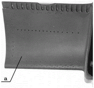
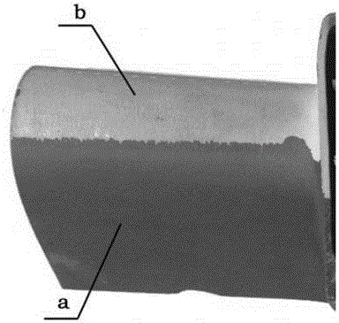
[0042] 1) First, tape the image 3 Protect the area 1 in order to verify the thinning of the metal bottom layer before and after the removal of the ceramic layer, and clamp the blade in the fixture;

[0043] 2) Install a nozzle with a diameter of 0.3mm in the spray gun;

[0044] 3) In the case of soft limit control, slowly move the spray gun with the nozzle to the corresponding blade surface, and set the target distance to 30mm;

[0045] 4) Set the pulse water pressure of the vortex pulse water jet to remove the ceramic layer to 40MPa, the nozzle moving speed to 0.02m / s, and the incident angle to 45°, turn on the vortex pulse water jet switch, and make the nozzle along the figure 1 The direction of the white arrow in figure 1 Change the line in the direction of the black arrow in to achieve the effect of continuous and layer-by-layer peeling of the ceramic layer.

[0046] 5) After the leaf basin of the blade is removed, the 180° rotation of the blade is realized through the...

Embodiment approach 2

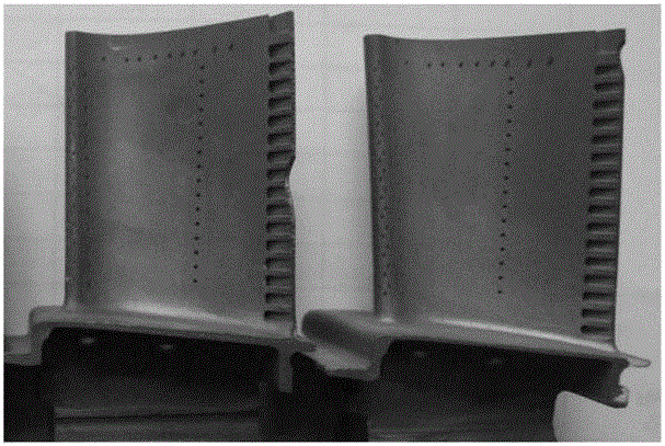
[0054] 1) First, clamp the two blades in the fixture;

[0055] 2) Install a nozzle with a diameter of 0.5mm in the spray gun;

[0056] 3) In the case of soft limit control, slowly move the spray gun with the nozzle to the corresponding blade surface, and set the target distance to 50mm;

[0057] 4) Set the pulse water pressure of the vortex pulse water jet to remove the ceramic layer to 60MPa, the nozzle moving speed to 0.05m / s, and the incident angle to 60°, turn on the vortex pulse water jet switch, and make the nozzle along the figure 1 reciprocate in the direction of the white arrow in ; at the same time, along the figure 1 Change the line in the direction of the black arrow in to achieve the effect of continuous and layer-by-layer peeling of the ceramic layer.

[0058] 5) After one side of the blade is removed, the 180° rotation of the blade is realized through the rotating shaft on the fixture;

[0059] 6) Utilize steps 3) and 4) to complete the removal of the ceramic...


PUM


Abstract

The invention discloses a method for removing ceramic layers of a thermal barrier coating. The method includes the steps that (1) a turbine working blade is clamped on a tool fixture; (2) a nozzle is mounted in a spray gun; (3) under the condition of soft limiting control, the spray gun with the nozzle is slowly moved to the current surface, where one ceramic layer is to be removed, of the turbine working blade, and the target distance is kept; (4) an eddy current pulse water jet switch is turned on, and the nozzle is made to reciprocate line by line in the axial direction of the turbine working blade; (5) after the ceramic layer on the current surface of the turbine working blade is completely removed, the blade is rotated by 180 degrees through a rotating shaft on the tool fixture; and (6) the step (3) and the step (4) are conducted to remove the ceramic layer on the other face. When the method is used for removing the ceramic layers, the ceramic layers are continuously stripped off layer by layer, a metal bottom layer is not damaged, the metal bottom layer does not need to be coated supplementarily, the procedures are simple, and re-coating of the ceramic layers is facilitated; and compared with a traditional mechanical sand blasting method, process parameters are accurately controlled in the method, and product quality consistency is high.

Description

technical field [0001] The invention belongs to the technical field of repairing ceramic layers of thermal barrier coatings of engine turbine blades, and in particular relates to a method for removing ceramic layers of thermal barrier coatings. Background technique [0002] At present, because the electron beam physical vapor deposition (EB-PVD) technology has the advantages of easy and precise control of the chemical composition of the coating, the columnar grain structure can be obtained, and the bonding strength between the coating and the substrate is high, it has been widely used in a variety of high-temperature protective coatings for turbine blades. The preparation and processing of the layer significantly improves the high-temperature oxidation resistance, corrosion resistance and heat insulation performance of the turbine blade, and prolongs the working life of the engine. [0003] However, the ceramic layer of the working blade with thermal barrier coating is parti...

Claims


Application Information

Patent Timeline
Patent Type & Authority Applications(China)
IPC IPC(8): B08B3/02
CPCB08B3/02
Inventor 王玉锋蒋文鸽汪波赵耀伟范凯李卫卫高贵忠李茂安
Owner AECC AVIATION POWER CO LTD
Why Eureka
Try Eureka