Welding repair method for surface defects of centrifugal composite roller

A centrifugal composite, roller shaft technology, applied in welding equipment, arc welding equipment, manufacturing tools, etc., can solve the problems of easy occurrence of pores, slag inclusion, shrinkage, affecting the quality of product appearance, and can not guarantee the shaft strength, etc., to achieve improvement. Welder labor intensity and environment, small product deformation, and the effect of improving the quality of finished products

Inactive Publication Date: 2017-01-04
ANSTEEL HEAVY MACHINERY CO LTD
View PDF6 Cites 6 Cited by
  • Summary
  • Abstract
  • Description
  • Claims
  • Application Information

AI Technical Summary

Problems solved by technology

[0002] Centrifugal composite ductile iron rolls are cast and compounded by the alloy material of the roll body and the ductile iron core material. During the casting process, the position of the riser shaft 4 is prone to defects such as pores, slag inclusions, and shrinkage porosity. The feeding position is removed, but there are still some defects remaining in the roll shaft body (such as figure 1 ), these defects affect the quality of the product perception, cannot guarantee the strength of the shaft, and even cause the roll to fail

Method used


Image

  • Welding repair method for surface defects of centrifugal composite roller
  • Welding repair method for surface defects of centrifugal composite roller
  • Welding repair method for surface defects of centrifugal composite roller

Examples


Embodiment Construction

[0019] Embodiments of the present invention are further described below in conjunction with the accompanying drawings:

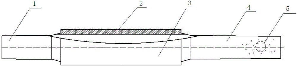
[0020] A welding repair method for surface defects of a centrifugal composite roll shaft, the specific method is as follows:

[0021] 1) Welding repair specification: use small-diameter Z308 nickel-based cast iron electrode, the welding repair current adopts DC reverse connection, that is, the workpiece is connected to the negative electrode, and the welding current is I=(29~34)×d, 2mm

[0022] In the formula: I—indicates the welding current; d—indicates the diameter of the electrode.

[0023] Small diameter Z308 nickel-based cast iron electrode, the welding core contains high nickel content, and the coating contains graphite. At room temperature, the weld metal with austenite structure can be obtained, with high tensile strength and good crack resistance.

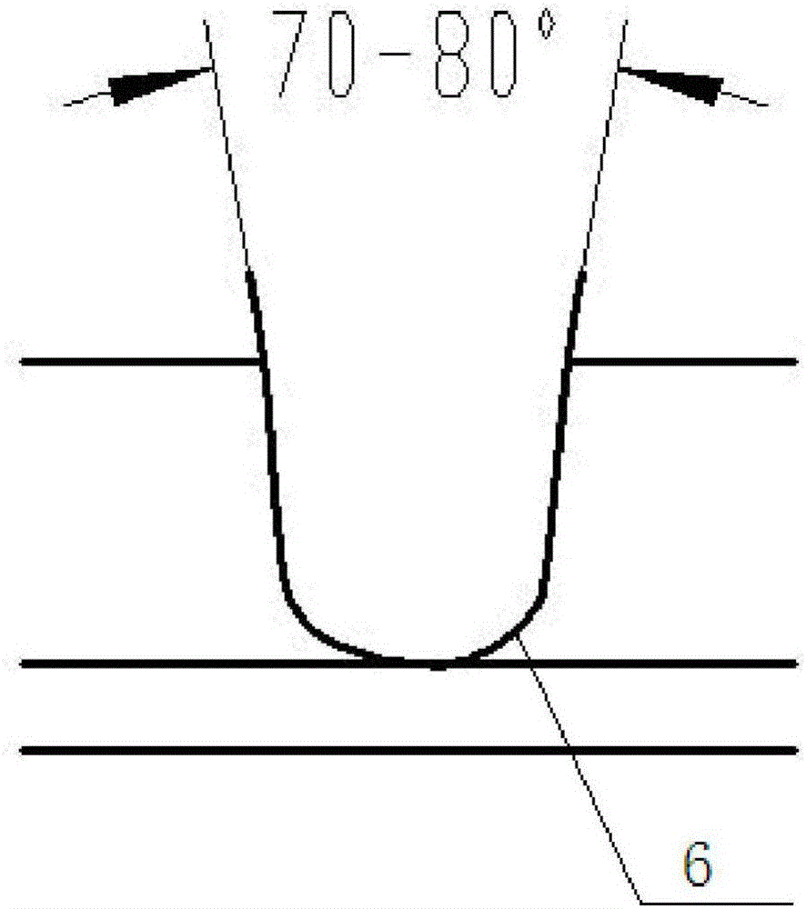
[0024] 2) Grinding the groove: Grind the groove on the defect of the roll shaft. The groove i...


PUM


Abstract

Provided is a welding repair method for surface defects of a centrifugal composite roller. The method specifically comprises the following steps that (1) welding repair specifications are selected; (2) a groove is ground and cleaned; (3) welding repair is carried out on the groove; and (4) the welding repair positions are ground. Damaged portions of a workpiece are subjected to welding repair recovery through electric arc heating and welding rod melting. The specifications of short sections, the intermittent mode, dispersed welding and multi-layer and multi-pass welding are followed in the welding process. Compared with the prior art, the welding repair method has the beneficial effects that pores, slag inclusion, shrinkage and other defects of the centrifugal composite roller are repaired through a cold welding method. The method has the advantages that neither preheating before welding nor thermal treatment after welding is needed, the deformation of welded products is small, the welding operation is easy, the number of assisting procedures before welding is small, the labor intensity of welders is relieved, and the welding environment is improved. The method is suitable for welding repair and recovery of various positions, mechanical cutting is easily carried out after welding is completed, and the quality level of finished products is greatly improved.

Description

technical field [0001] The invention relates to a welding method, in particular to a welding repair method for defects of pores, slag inclusions and shrinkage porosity on the shaft surface of a centrifugal composite roll. Background technique [0002] Centrifugal composite ductile iron rolls are cast and compounded by the alloy material of the roll body and the ductile iron core material. During the casting process, the position of the riser shaft 4 is prone to defects such as pores, slag inclusions, and shrinkage porosity. The feeding position is removed, but there are still some defects remaining in the roll shaft body (such as figure 1 ), these defects affect the quality of the product perception, cannot guarantee the strength of the shaft, and even cause the roll to fail. Contents of the invention [0003] The purpose of the present invention is to solve the above-mentioned problems existing in the prior art, and to provide a welding repair method for the surface defe...

Claims


Application Information

Patent Timeline
Patent Type & Authority Applications(China)
IPC IPC(8): B23K9/04B23K9/235
CPCB23K9/048B23K9/235
Inventor 张福海刘绍昌郑伟李艳红杨林利刘娜
Owner ANSTEEL HEAVY MACHINERY CO LTD
Why Eureka
Try Eureka